Category Archives: Tutorials


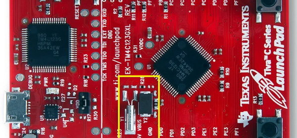
Tiva C Clock System

The clock system of a microcontroller is a fundamental element. Clock system provides the heart-beat needed to keep applications running in a synchronous manner. In the case of Tiva C micros the clock system is as much as sophisticated and elaborate as with any other ARM micros. In this post we will explore this basic block of Tiva C micros. We will see that the clock system is a network of different clock sources and internal units that are intertwined in a complex but easy manner.

Read more

MAX7219 serial seven segment displays for ESP8266

Seven segment LED displays are brighter, more attractive and provide a far viewing distance as well as a wider viewing angle as compared to LCD displays. The major drawback of using seven segment LEDs is they are resource-hungry. Our MAX7219 based serial seven segment LED display modules allows you to add 8 digits of seven segment LED displays to your microcontroller project using only 3 I/O pins, and provides full control of all the digit segments including decimal points. You can even cascade two or more of these modules together without sacrificing any extra I/O pin. Since it requires only

Read more

The World of TI’s Tiva C MCUs

Most of us who work with electronics know the name of Texas Instruments (TI) as a manufacturer of several important digital and analogue ICs as well as fancy sophisticated scientific calculators. However many people don’t know that TI is also a manufacturer of some of industry’s best microcontrollers. TI’s portfolio of micros is pretty large. ARM micros are getting popular day-by-day and on that family of micros TI has some of the best devices one can imagine. One such family from TI is the Tiva C series. Enter the TM4C123x Tiva C micros – one of the best possible combination

Read more

Hookup guide for 16×32 RGB LED panel – Part 3

In this third part of the 16×32 RGB LED panel hookup guide, we will run some demo sketches with Arduino Uno to display basic text and animation on the 16×32 RGB LED matrix. These demo programs use Adafruit’s RGBMatrixPanel Library are found inside its Example folder. The wiring between the RGB panel and Arduino Uno is discussed in detail in the previous parts of this 3-part tutorial. Click here to read Part 1 of this tutorial Click here to read Part 2 of this tutorial Click here to buy this kit from our US Tindie store Get this RGB panel kit

Read more

Hookup guide for 16×32 RGB LED panel – Part 2

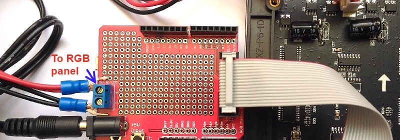
This is the second part of the 3-part article on how to hookup our 16×32 RGB LED panel kit to Arduino Uno. Click here to read the first part Step 3: Connecting the LED panel to the RGB connector shield The pin arrangement of the 2×8 IDC port (IN) on the back side of the RGB panel are shown below (image taken from Adafruit’s tutorial page). The 12 I/O pins of Arduino that are used to drive these signal lines are listed in the following table.

Read more
« Older Entries Recent Entries »