Making a digital capacitance meter using microcontroller
|
|
Capacitors are one of the most common passive electrical components that are extensively used in all kinds of electronic circuits. In this project, we will discuss a technique of building a digital capacitance meter using a PIC microcontroller. This project can measure capacitance values from 1 nF to 99 ?F, with a resolution of 1 nF. The technique is based on measuring the time elapsed when a capacitor is charged to a known voltage through a series resistor. The microcontroller used in this project is PIC16F628A.

Capacitance meter
Theory
This capacitance meter is based on the principle of charging a capacitor through a series resistor. In a series RC circuit, as shown in the figure below, the voltage across the capacitor increases exponentially as it charges. Lets assume that initially the capacitor was fully discharged. When Vin is applied across the RC circuit, the capacitor starts charging and consequently, the voltage (Vc) across it increases from 0 towards Vin in an exponential way, as shown in the right side of the figure. The equation provided in the figure describes how the voltage across the capacitor changes with time. If we know the time that is required for the capacitor to charge up to a known voltage then we can solve this equation for C, knowing the value of R.

Capacitor voltage increases exponentially with time
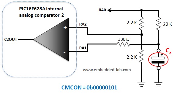
The idea of measuring the time elapsed when the capacitor is charged from 0 to a known voltage can be implemented with any microcontroller. Here, we are using the PIC16F628A microcontroller, which has two built-in analog comparators. In this project, we are using the Analog Comparator 2 and TIMER2 modules to determine the time required by the capacitor to charge from 0V to 0.5Vin. The positive and negative inputs of the Analog Comparator 2 are externally accessible through RA2 and RA1 pins of PIC16F628A, respectively. In the figure shown below, two 2.2K resistors creates a voltage divider that sets the positive input (RA2) of the comparator to half of the voltage applied to RA0 pin. The negative input (RA1) of the comparator goes to the positive end of the capacitor through a 330? resistor. The resistor is used to discharge the capacitor prior to its measurement by setting RA1 low. When a voltage is applied to the RA0 pin, the capacitor (Cx), initially fully discharged, is charged through a 22K resistor. When the RA0 pin is just set high (say around 5V), the output of the comparator is high as the positive input of the comparator is at higher voltage (about 2.5V) than the negative input, which is close to 0V as the capacitor is fully discharged. Now the capacitor starts charging through the series resistor (22K) and when the voltage across it exceeds half of the voltage at RA0 pin, the comparator output is flipped to low. The comparator interrupt flag (CMIF) is set whenever there is a change in the output value of the comparator. The Timer2 module is used to compute the time elapsed between when RA0 is set high and the comparator output goes low. This is the time required by the capacitor to charge from 0V to half of the supply voltage.

RC circuit and comparator inputs
By knowing the value of the charging resistor (in this case it is 22K) and the charging time (from Timer2), we can now solve the capacitor equation, mentioned above, to compute C. Here’s the mathematics involved in the process. For simplicity, the Timer2 is initialized with value 104 so that it overflows in 256-104=152 clock cycles (the number 152 comes from the math shown below). If we use 4.0 MHz external clock source, this is equivalent to 152 ?sec. By doing so, the calculations are much simplified as described below. The final equation suggests that for the given arrangement, the measured capacitance (in nF) is simply 10 multiplied by the number of times the Timer2 overflows, starting from 104 every time. This gives a resolution of 10nF, which can be further improved to 1nF by considering the value of Timer2 itself at the instant when the comparator output switches to low and the Timer2 module is stopped.

Calculating C from charging time
The complete circuit setup for this project is given below. The pins RA0-RA2 goes to the voltage divider and capacitor charging circuit described earlier. The measurement begins when the Start push button is pressed. The measured capacitance is displayed on a standard character LCD. The +5V power supply is derived from a 9V battery using a LM7805 regulator IC. I am using my DIY Experimenter’s I/O board for the LCD part of this project, and my 18-pin PIC16F board for easy prototyping with the PIC16F628A microcontroller.

Capacitance meter circuit

Voltage divider and RC circuit

Complete setup of the experiment
Software
The firmware for the PIC16F628A microcontroller is written in C and compiled with mikroC Pro for PIC compiler. The maximum value of measurable capacitance is set to 99.99 uF. The program displays “Out of Range” message while measuring capacitance value higher than this. Normally, the RA0 pin is set to low so that the capacitor gets discharged through the 22K resistor before measurement. When the Start button is pressed, the RA1 pin is set to low for 2 sec which expedites the discharging process as the capacitor discharges much quicker through the 330 ? resistor, as compared to 22K. Next, the Timer2 is initialized and the corresponding interrupt is enabled. RA1 and RA2 are configured as analog comparator inputs. Then RA0 is set to high and Timer2 is turned on. As soon as the comparator output (CMCON.C2OUT) flips from high to low, the Timer2 module is stopped. The time required by the capacitor to charge from 0V to half of the voltage across the RC circuit is computed from the number of times the Timer2 has overflown and the final value of the Timer2 register itself. This timing information is used to estimate the capacitance value using the math described in the theory section.
/* Project: Capacitance meter Description : CapMeter based on RC time constant MCU: PIC16F28A Oscillator: HS, 4.0000 MHz external Written by: Rajendra Bhatt (www.embedded-lab.com) */ // LCD module connections sbit LCD_RS at RB2_bit; sbit LCD_EN at RB3_bit; sbit LCD_D4 at RB4_bit; sbit LCD_D5 at RB5_bit; sbit LCD_D6 at RB6_bit; sbit LCD_D7 at RB7_bit; sbit LCD_RS_Direction at TRISB2_bit; sbit LCD_EN_Direction at TRISB3_bit; sbit LCD_D4_Direction at TRISB4_bit; sbit LCD_D5_Direction at TRISB5_bit; sbit LCD_D6_Direction at TRISB6_bit; sbit LCD_D7_Direction at TRISB7_bit; sbit Va at RA0_bit; sbit Switch at RB0_bit; char message1[] = "Capacitance"; char message2[] = "Meter"; unsigned int T_Value, Num; unsigned short i, j, TimerValue, OverRange = 0; char Capacitance[] = "00.000 uF"; void interrupt(){ if(PIR1.TMR2IF){ TMR2 = TimerValue; Num ++; if(Num > 9999) OverRange = 1; // Range is 99.99 uF PIR1.TMR2IF =0; // Clear TMR0 interrupt flag } } void Display_Cap(unsigned int n){ Capacitance[0] = n/10000 + 48; Capacitance[1] = (n/1000)%10 + 48; Capacitance[3] = (n/100)%10 + 48; Capacitance[4] = (n/10)%10 + 48; Capacitance[5] = (T_Value*10)/153 + 48; Lcd_Cmd(_Lcd_Clear); Lcd_Out(1, 1, "C = "); Lcd_Out(1, 5, Capacitance); } void reset(){ TRISA = 0b00000100; CMCON = 7; RA1_bit = 0; Delay_ms(2000); TRISA = 0b00000110; CMCON = 5; } void main(){ char cap_size; TRISB = 0b00000001; PORTB = 0; TRISA = 0b00000110; OPTION_REG.T0CS = 0; INTCON.GIE = 1; //Enable global interrupt INTCON.PEIE = 1; //Enable peripheral interrupt // Configure Timer2 module PIE1.TMR2IE = 1; // Enable Timer2 interrupt T2CON = 0; // Prescaler 1:1, and Timer2 is off initially PIR1.TMR2IF =0; // Clear int bit // Configure Comparator module CMCON = 5; // Independent comparator between RA1 (-) and RA2(+) Lcd_Init(); Lcd_Cmd(_Lcd_Clear); Lcd_Cmd(_LCD_CURSOR_OFF); Lcd_Out(1, 1, message1); Lcd_Out(2, 1, message2); delay_ms(2000); Lcd_Cmd(_Lcd_Clear); Lcd_Out(1, 1, "C = "); Lcd_Out(1, 5, Capacitance); Va = 0; TimerValue = 108; // 104 + 4 additional clock cycles delay on branching to ISR while(1){ if(!Switch) { Num = 0; OverRange =0; Lcd_Cmd(_Lcd_Clear); Lcd_Out(1, 1, "Testing."); Lcd_Out(2, 1, "..."); TMR2 = TimerValue; // Initialize Timer2 Va = 1; //apply voltage T2CON.TMR2ON = 1; // start timer while(CMCON.C2OUT) { if(OverRange) break; } T2CON.TMR2ON = 0; // stop timer T_Value = TMR2 - TimerValue; // T_Value is used for improved resolution Va = 0; //--------------------------------- if(!OverRange){ Display_Cap(Num*10); } else{ OverRange = 0; Lcd_Cmd(_Lcd_Clear); Lcd_Out(1, 1, "Out of Range!"); } reset(); } } } |
Download complete source and HEX files
Output
A variety of capacitance values are tested with this capacitance meter and the results are found pretty consistent with their rated values. Here are some snapshots showing the meter in action.

Measuring 1 nF rated capacitor

Measuring 15 nF rated capacitor

Measuring 100nF rated capacitor

Measuring 10 uF rated capacitor

Capacitor rated 22 uF

Capacitor greater than 100 uF
Summary
The charging phenomenon of a capacitor through a series resistor was discussed and used to construct a very basic capacitance meter. The PIC16F628A microcontroller was used to control the charging/discharging process of the capacitor. With the help of a built-in analog comparator and a timer module, the PIC microcontroller computed the time required by the capacitor to build a known voltage across it when charged through a given series resistance. Using all these information, the microcontroller computed the capacitance. The measured output was found to be reasonably consistent with the rated value when tested with a wide range of capacitance values.
Note: All capacitors, but specifically high voltage capacitors, must be first properly discharged prior to measurement to avoid any damage to the capacitance meter circuit.
|
|
This is very excellent project . Thanks for posting and sharing this project .
how to measure 0.0001 to 33000uf or any unknown capacitance . how to change circuits and codes plz help……………..
what is configuration word for pic16f628a , is it necessary to write it above the program or not ? How to
open window (step by step) to write program in mikroc. which version is suppose to use?
sir i am new in programming field, in your program at begining , #include is not written.
ts there any need to write something from our side in your given program before burning the microcontroller.
This is very excellent project .It works……..
I did not understand how do you calculate 256 and 104? What is the definition of 256?Can you explain please…
The value of C is 10N , how you calculate it , my calculation leads to another value.
The formula you calculated for C , how it comes 10N. I do the calculation its not coming 10N. Please explain.
Hi. I have built this thing and its great. But I just dont understand one simple thing in your code.
Capacitance[0] = n/10000 + 48;
Capacitance[1] = (n/1000)%10 + 48;
Capacitance[3] = (n/100)%10 + 48;
Capacitance[4] = (n/10)%10 + 48;
Capacitance[5] = (T_Value*10)/153 + 48;
Please explain to me whats going on in this part of the code from the Display_cap() function. My email ID is usama1@ualberta.ca
This part extracts individual digits from a multi-digit number and convert each digit to its ASCII value so that it can be displayed as a character on LCD. You must add 48 to a number to get its ASCII value. For example, the ASCII value of ‘5’ is 53, so you need to add 48 to 5 to get that value. This happens because 0 has ASCII value of 48 and 1 has 49, 2 has 50, and so on. % indicate modulo operation that finds the remainder after division.
Hey.
Very nice project.
But when i use this meter for measuring capacitors. I have the value divided by 10.
Examples: capacitor 10uf capacitance give me 1 uf!
Where is the problem please? ?
nice…how to change capacitances range (1pf to 1uf) ?
Please how can i modify the code in order to have a capaciatnce meter that mesure picofarad capacitances range (0.001pf to 99.99 pf)
Can somebody tell me the names of the components used to design this project???( microcontroller based capacitance measuring meter)
Thanks for your nice article. Can you please explain what are RA0 .. RA2 are in the diagram “Capacitance meter circuit”?
I have calibrated and measured single capacitors and trusted the meter. Then I had to bundle a few caps in parallel and I discovered a problem. I have two capacitors, each measures 1.024 nF on the meter. I wire them in parallel and expect the measurement to be 2.048 nF but the meter measures 2.020 nF! I did the repeat the procedure several times and also on three other DMM’s and although they had only had 3 1/2 and 4 1/2 digits they measured the bundled cap correctly at exact twice the value of a single cap at 2.048 nF.
This indicates to me that this meter is not linear and can not be trusted no matter how many digits it displays. Is the formula properly programmed in the PIC? What is going on?
sir can i use this project to measure capacitors from 1 pf to 1000 pf by changing the components and codings
pls reply me my email is vipinkp77@gmail.com
Very nice Work……….. sir. but how to measure up to 200uf unknown capacitance . how to change circuits and codes plz help……………..
good afternoon sir,dis project is very impressive.pls can you send me the block diagram and i need more explanation on how the digital capacitance works.tanx
Thanks very much.please can you also post one for measuring inductance and frequency using pic16f628a?thanks in advance
hi can you please justfy the resistances values ??? why exactly those values and can you explain the methode showen up about how to find the value of rhe capacity based on time ?? i really didn’t undertsand the last two lines and thank you prevsly 🙂
Hi thanks for posting this project .. Can u justify the values of the resistors used please ?
It a great work, Thank you for sharing. Did you have a circuit for inductor ?
Hi! this is a good proyect, thaks for shared.
Is it possible to measure capacitance of solid using above capacitance meter?
What display are you using? HD44780 controller or KS0066?
Very very nice Work………..
Marc P , you change R=22k to 23.4k .
where can i find the basic version ( for AVR microcontroller ) of the source code for the digital capacitance meter?
can you write this program with BASIC language for avr microcontroller (ATMEGA 32 )
Hey Raj!
Nice project, i tried it and a capacitor with 22 uf give me 28.601uF… what’s wrong?? is it normal?
thank you!
marC:)
where can i find the assembler version of the source code for the digital capacitance meter?
interesting! definately going to do this one…
Very good project!!! Is it possible to extend the range of the capacitance??
thank you!
marC:)
[…]Nice project!Actually I did not understand calculation of 256.What is the definition of 256?Can you explain please?…
?t is nice project.Actually I did not understand how do you calculate 256 and 104? What is the definition of 256?Can you explain please…
Pingback: PIC16F … 18 PIN devices | Zardynamix
Pingback: Polish your understanding of capacitors by building this meter | CisforComputers
Pingback: Fabriquer un capacimètre | Actu-Radioamateur Fabriquer un capacimètre | L'actualité radioamateur, et nouvelle technologie…
Pingback: Polish your understanding of capacitors by building this meter « Hackaday « Cool Internet Projects
Pingback: Polish your understanding of capacitors by building this meter » Geko Geek
Pingback: Polish your understanding of capacitors by building this meter - Hack a Day
Man you are great! Very impressive!! Thanks a lot for sharing that! Lots of people are following you! Keep going!
What a great project! This is exactly what I have been needing to experiment with a new pc board etch technique. And it is with a microprocessor that I have in stock. I can’t wait to get started.