MM74C922N-based encoded matrix keypad
|
|
Matrix keypads are an excellent way of providing user input data into microcontroller-based systems. Keypads find applications in remote controls, standalone data-loggers, security systems, door entry systems, calculators, microwave ovens, etc. They are usually implemented as pushbutton switches arranged in a row and column matrix format to reduce the number of I/O connections. For example, a 16-switch keypad is arranged in a 4 X 4 matrix format requiring 8 I/O connections. A pressed key is detected and identified by scanning the keypad to look for a short circuit condition between a row and a column wire. The keypad scanning can be done either by polling or by means of an interrupt routine. In the polling approach, the scanning process is repeated in a continuous loop, which results in waste of CPU time. The interrupt-approach is more efficient and it notifies the processor when there is a keystroke. Another approach of interfacing a keypad to the microcontroller is by using a dedicated keypad encoder IC, which further reduces the I/O connections and makes the interface much simpler. In this project, we are building a simplified 16-switch keypad using the MM74C922 encoder chip, which converts a key switch closure to a 4-bit nibble output.
MM74C922N based encoded keypad
Theory
The MM74C922 chip is available in 18-pin DIP and 20-pin SOIC packages. This project uses the DIP version, which has the pin configuration as shown below.
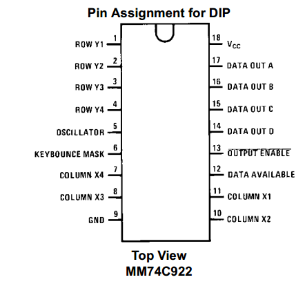
Pin diagram of MM74C922 DIP
The MM74C922 encoder implements all the logic necessary to interface a 16-key switch matrix to a digital system. The encoder chip continuously scans the keypad waiting for a key press. When a switch is pressed, it provides a 4-bit nibble corresponding to the pressed switch at its output pins D, B, C, and A (14-17). The chip has a built-in debounce circuit, which requires a single external capacitor to be connected to Keybounce Mask pin (6) to operate. The value of the capacitor depends on the required debounce time. When a valid key press is detected and the key bounce circuit times out, the encoded data is latched to the output port and the Data Available (DAV) pin (11) goes high. The DAV pin falls back low when the pressed key is released. The DAV output can be thus used as an interrupt signal for the processor when there is a keystroke. The latched output remains active at pins A through D even after the key is lifted. New data will be available at a new keystroke. The chip also has the two-key rollover feature, which disregards any second key press during an active keystroke. The keypad scanning rate is also configurable through an external capacitor connected to the Oscillator pin (5). The graphs below show the dependency of debounce time and scan rate on the respective capacitor values.
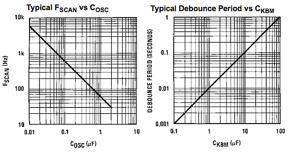
Debounce time and scan rate as functions of capacitors
Circuit diagram
The circuit diagram of this project is shown below. The capacitor values selected for Debounce Mask and Oscillator pins are 1uF and 0.1uF, respectively. This sets the debounce time to approximately 10 ms and the keypad scan rate to about 600 Hz (from the above graphs). An LED connected to the DAV pin serves as a visual indicator when a valid key press is detected.
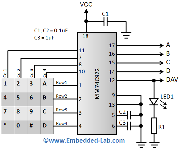
16-switch encoded keypad circuit diagram
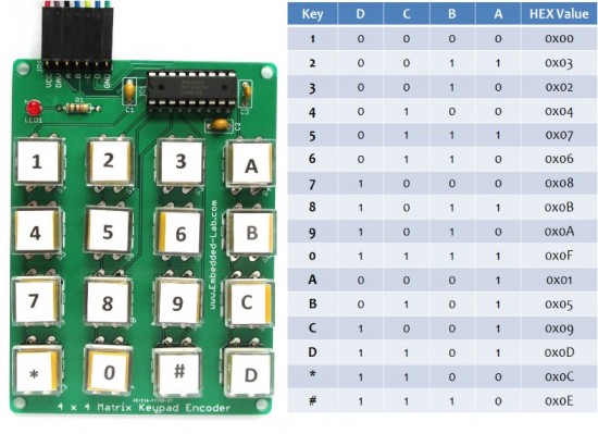
The 16 switches in the above arrangement are named 0-9, *, #, and A-D. The following table shows the HEX values of the output nibble corresponding to each key presses.
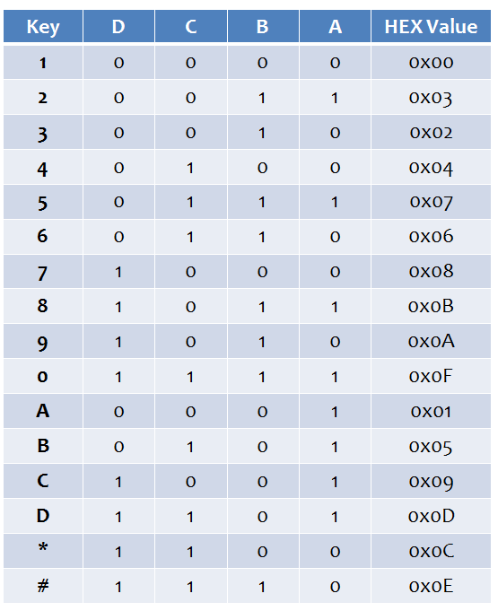
Table showing the nibble output for each individual key press on the matrix
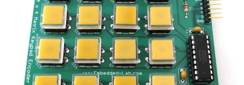
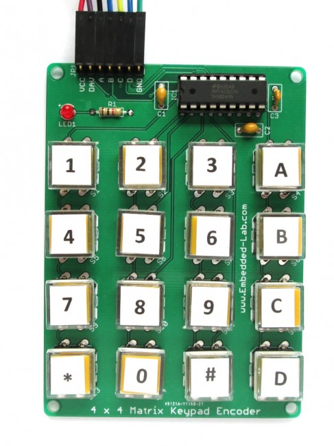
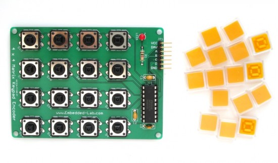
The following pictures show assembled circuit board of this project. I am using 12mm x 12mm tact switches with plastic caps and transparent covers on top.
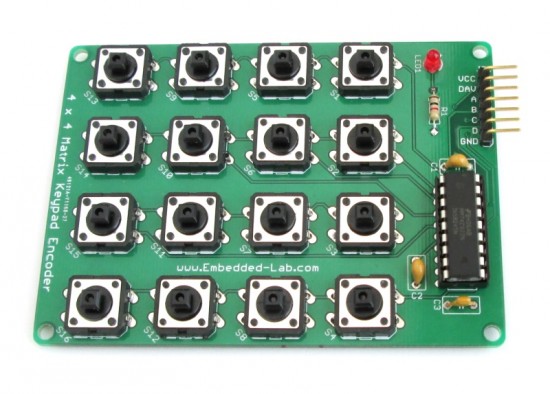
Assembled encoded matrix keypad uses 12mm x 12mm tact switches
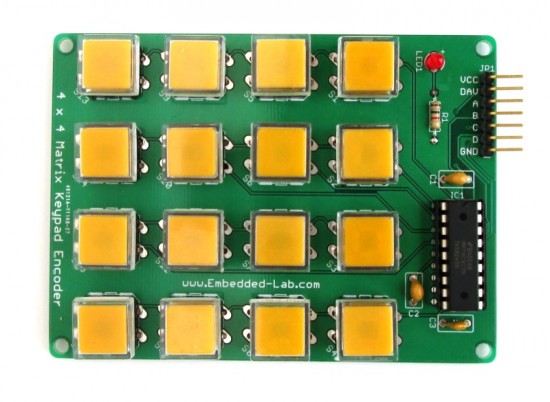
Assembled encoded matrix keypad with caps and plastic covers on top of switches
We can put small paper cuts between the yellow cap and top plastic cover to label the keys like shown below.
Keypad labeling
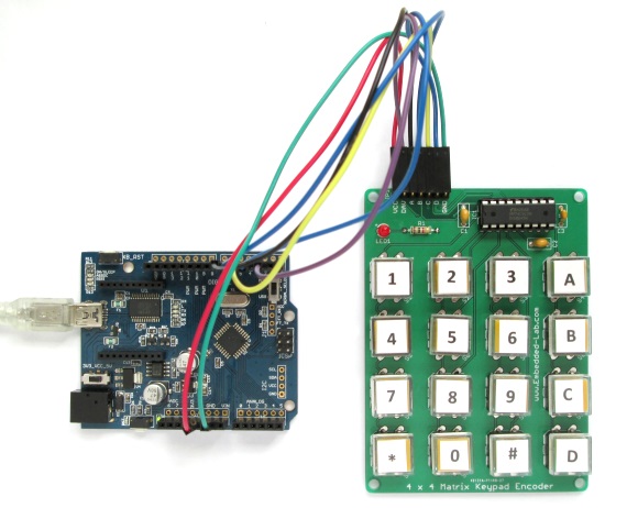
Interfacing example
In this section, I will demonstrate how to interface this matrix keypad to a host microcontroller. I am using Arduino platform here but the same logic can be extended to any other microcontroller platform. The keypad is powered with 5V supply from the Arduino board. The DAV output pin goes to INT0 (digital I/O pin 2) pin of the Arduino board. This means that whenever a keystroke is detected, the Arduino will be interrupted to read the pressed key value. The encoder output pins A, B, C, and D are connected to Arduino digital I/O pins 7, 6, 5, and 4, respectively. The following picture shows the complete setup of this demo project. The detected keystroke is displayed on Serial Monitor window on PC.
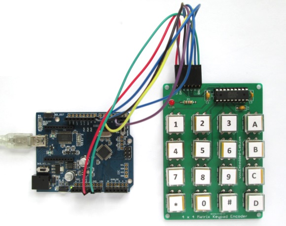
Interfacing with Arduino board
The Arduino sketch for this demo project is very simple. An interrupt service routine is written to read the encoder output (A-D) when a keystroke is detected (at the falling edge of the DAV pulse). The encoded nibble are mapped to the key names on the matrix through a look-up table.
The following screenshot is of the serial monitor window on my PC that shows the detected keystrokes and their names and hex values, as discussed before.
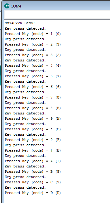
Pressed keys displayed on Serial Monitor window
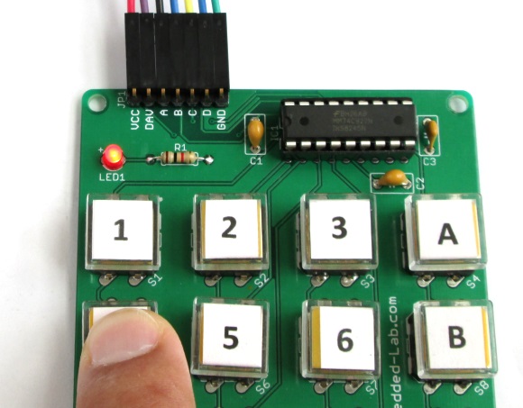
Led turns on when a key is pressed
You can also buy the 4 x 4 encoded keypad from our Tindie store. You will receive an assembled and tested board with 16 sets of free plastic caps and transparent covers.
16-switch encoded keypad kit
Quick reference sheet
|
|
DSo you still sell the chip mm74c922 I have a project ready built that just needs this chip. David Marsh
PS Variables “output” and “press_status” should have the “volatile” attribute, because they are set in an interrupt service routine.
The code would have been cleaner and tighter if port manipulation had been used (e.g. “output = PIND;” in Read_Data()).
Cheers,
NV1T
Nice project. The code would be considerably cleaner if you had used port manipulation (e.g. “output = PIND;”) in Read_Data();
Could you tell me the part no. or even the manufacturer of those buttons? I have been looking for something like that for a while and haven’t found anything.
Thanks.