Soldering the SPI7SEGDISP8.56 serial 8-digit seven segment LED display kit
|
|
SPI7SEGDISP8.56 is a MAX7219 based serial 8-digit seven segment LED display module. With this display module, you can easily add 8 digits of seven segment LED displays to your project using only 3 I/O pins, and provides full control of all the digit segments including decimal points. You can even cascade two or more of these modules together without sacrificing any extra I/O pin. You can buy SPI7SEGDISP8.56 display kit on Tindie for only $12.00. SPI7SEGDISP8.56 PCB is double layer. The top layer consists of two 4-digit CC LED display modules (Disp1 and Disp2) arranged in a row and header connectors (JP1 and JP2), whereas the bottom layer is one where the MAX7219 chip and other passive components reside.

Assembled SPI7SEGDISP8.56 board top and bottom view
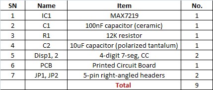
The SPI7SEGDISP8.56 kit contains 9 items in total which are listed here.
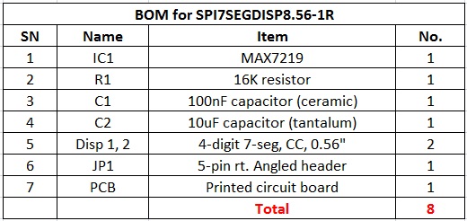
Contents of kit
Here are the soldering instructions to assemble the kit.
Step 1
Keep in mind that you have to solder all the components on the bottom PCB layer first. This includes IC1, C1, C2, and R1. Remember that C2 is a polarized capacitor so the positive lead (usually longer one and is marked too) should go to the hole that is marked with ‘+’ on PCB. The pin number 1 of IC1 is also marked on the bottom silkscreen. Use it to correctly place the MAX7219 IC.

PCB- Top and Bottom view

Solder components on bottom layer first. C2 is polarized tantalum capacitor with positive lead pin marked as ‘+’. Pin 1 of MAX7219 is also marked on bottom silkscreen.
Step 2
Next step is to solder the two display modules and header pin on top layer. Before that cut the long leads of all the bottom layer components (C1, C2, and R1) that show up in the top layer.

Cut long leads of C1, C2, and R1 before placing the display modules on top

Solder top layer components after finishing the bottom layer components
JP2 is optional and is required only if want to cascade another SPI7SEGDISP8.56 module. At last, you can peel off the plastic cover from the display modules for better readability.

Peel off plastic cover from the display for better readability

Assembled SPI7SEGDISP8.56 board
Links
SPI7SEGDISP8.56 buying link – Red color
SPI7SEGDISP8.56 buying link – Yellow color
SPI7SEGDISP8.56 buying link – Green color
|
|
hello
i want 6 digit 7 segment in small size with high brightness
can u help me?