Tag Archives: DIY Geiger counter


ESP8266 powered DIY Geiger Counter

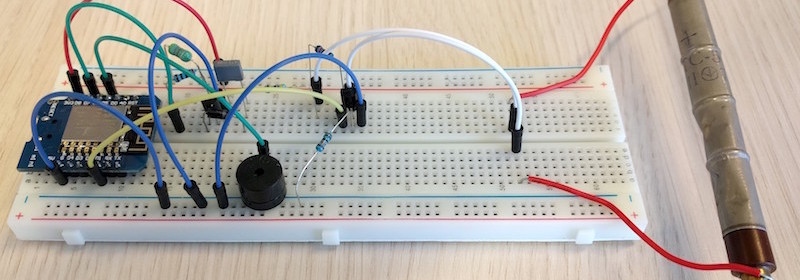
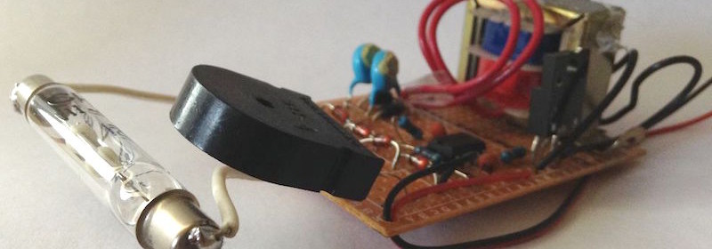
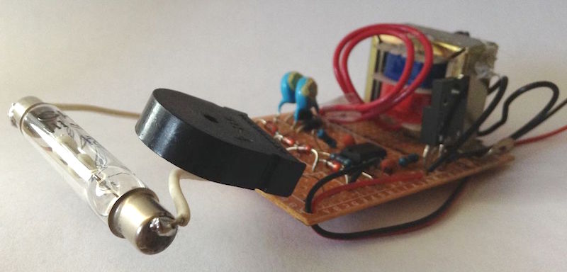
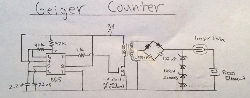
DIY Geiger counter projects are very popular among hobbyists. They all use a Geiger-Muller (GM) tube, which is filled with an inert gas such as helium, neon, or argon at low pressure, to which a high voltage is applied. The tube becomes electrically conductive when it is impacted by a high-energy particle or photon. Earlier, we have seen a very simple Geiger counter circuit using 555 timer, where the timer IC is configured as an astable multivibrator to drive a step-up transformer through a MOSFET in order to generate the high voltage required for the GM tube. This ESP8266-powered DIY Geiger counter by Hackaday user biemster, however, avoids the use of any step up transformer for the high-voltage generation; it rather achieves the same using a simple MOSFET switching circuit comprising of an inductor, a diode and a capacitor. The switching circuit is driven by a PWM waveform from an ESP8266 I/O pin. The use of ESP8266 also provides network connectivity to access the radiation and dose information via web interface, MQTT, or ICMP packets.

ESP8266 based Geiger counter

ESP8266 based Geiger counter

The high voltage output from the MOSFET switching circuit depends on the duty cycle of the PWM signal, which can be adjusted in the software. The complete code for this project can be downloaded from Github. LTspice simulation results showed that with a PWM frequency of 10 kHz, the output voltage has minimum ripple on it. The PWM generation, ESP8266 pin assignments, and calibration of the duty cycle to derive an optimal high-voltage output for the tube are all provided by the author in one MicroPython library.

DIY Geiger Counter using 555

Geiger counters are used to detect beta particles and gamma rays radioactive emissions. The counter consists of a tube filled with an inert gas such as helium, neon, or argon at low pressure, to which a high voltage is applied. The tube becomes conductive of electricity when it is impacted by a high-energy particle or photon. Tanner_Tech‘s Instructable shows how to build the simplest 555 timer based DIY Geiger counter using minimal electronic components.

Geiger counter using 555 timer

Geiger counter using 555 timer

Tanner_Tech‘s design uses 555 timer IC as an astable multivibrator to drive a step-up transformer through a MOSFET in order to generate the high voltage required for the Geiger tube. A piezo element placed in series with the Geiger tube acts as a detector, which clicks every time the ionization event occurs inside the tube due to high energy particles.

Circuit diagram of 555 timer based Geiger counter

Circuit diagram of 555 timer based Geiger counter

Following video shows this device working.

Too make this Geiger counter work, there needs to be two parts of this circuit; the high voltage power supply, and the detector circuit. In the diagram above, the high voltage circuit consists of a 555 timer driving oscillator driving a transformer. The 555 timer generates a square wave that, through a resistor, turns on and off a MOSFET transistor. This MOSFET drives a small step up transformer. The output of the transformer is then fed into a voltage doubler where the voltage is boosted to about 500 volts. Then, the voltage is regulated through a series of 4 100v zener diodes to the Geiger tube’s recommended 400 volts.

For the detector circuit, the Geiger tube’s anode is wires directly to the 400 volt power supply. In between the cathode of the tube and ground, I placed a piezo electric element. This converts the small current flow from the Geiger tube to a audible click.