Arduino pin monitor shield
Carsten Tonn-Petersen has designed this Arduino pin monitor and tester shield to assist his prototyping work with Arduino. The key features of this shield is it provides one LED for every single I/O pin and can be used with Arduino Uno, Leonardo, Mega, Due, and Mini. The shield also features one tact switch and one toggle switch for digital inputs along with two potentiometers for simulating analog input voltages during prototyping.
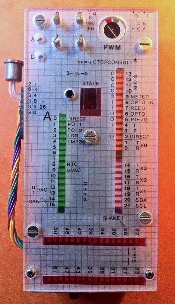
Arduino tester shield
The complete list of features as Carsten has mentioned about his Arduino pin monitor and tester shield are listed below:
- One LED for every single input or output
- Can be used with Uno, Leonardo, Mega, Due, Mini, etc.
- Also fits with my universal I/O board
- Power taken from Arduino 5V and 3.3V outputs, and the Vin
- Load on any pin is 10 kohm or more
- LED intensity proportionally reflects the pin voltage or duty cycle
- Builtin inputs and outputs for testing new ideas:
- One pushbutton (P) to digital input
- One toggle switch (T) to digital input
- Two potentiometers (1, 2) to two analog inputs
- 4 digital outputs to 7-segment number display (e.g. for program STATE output)
- Very small moving coil voltmeter on PWM output
- Piezo loudspeaker on PWM output
- 4 digital outputs to open-drain MOSFET (builtin flyback diodes)
- One opto-isolated digital input
- One opto-isolated digital output (not for 230 VAC)
- One direct analog input via miniature LEMO coax connector
- One direct digital I/O/PWM via miniature LEMO coax connector
- One reed-relay (no coil) to digital input
- One mercury shake alarm to digital input
- One TMP36 temperature sensor to analog input
- One electret microphone to analog input (x 100 gain)
- One NTC resistor to analog input (linearized)
- One light-dependant resistor to analog input
- All inputs and outputs can be made passive to enable inputs from other sources
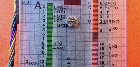
- LED’s grouped in 16 for analog I/O, 14 for digital I/O/PWM, 8 for digital I/O/Tx/Rx and 32 digital I/O. In total 70 LEDs.
- All LEDs are very high efficiency white SMD types with coloured film on top, according to the group.
- The LEDs cathode reference can be adjusted down to -2V: LEDs will start to light up when pin voltage goes positive.
- The cathode reference is divided into one for analog and one for digital, adjusted individually
- Maximum input voltages can be selected between 5V or 3.3V to fit with DUE board
- Voltage for internal circuits and steppermotor outputs can be selected between 5V and Vin
- IC-sockets and Arduino pins are all gold plated
- LEMO I/O, Shake-sensor, NTC, TMP36, microphone and piezo-speaker are in a detachable separate module
Visit Carsten’s project page for more details.