Tiva C Clock System
|
|
The clock system of a microcontroller is a fundamental element. Clock system provides the heart-beat needed to keep applications running in a synchronous manner. In the case of Tiva C micros the clock system is as much as sophisticated and elaborate as with any other ARM micros. In this post we will explore this basic block of Tiva C micros. We will see that the clock system is a network of different clock sources and internal units that are intertwined in a complex but easy manner.
Clock System Basics
Just as with any modern era micros Tiva C micros have several clock sources. Some of these sources are external while most clock sources are internal.
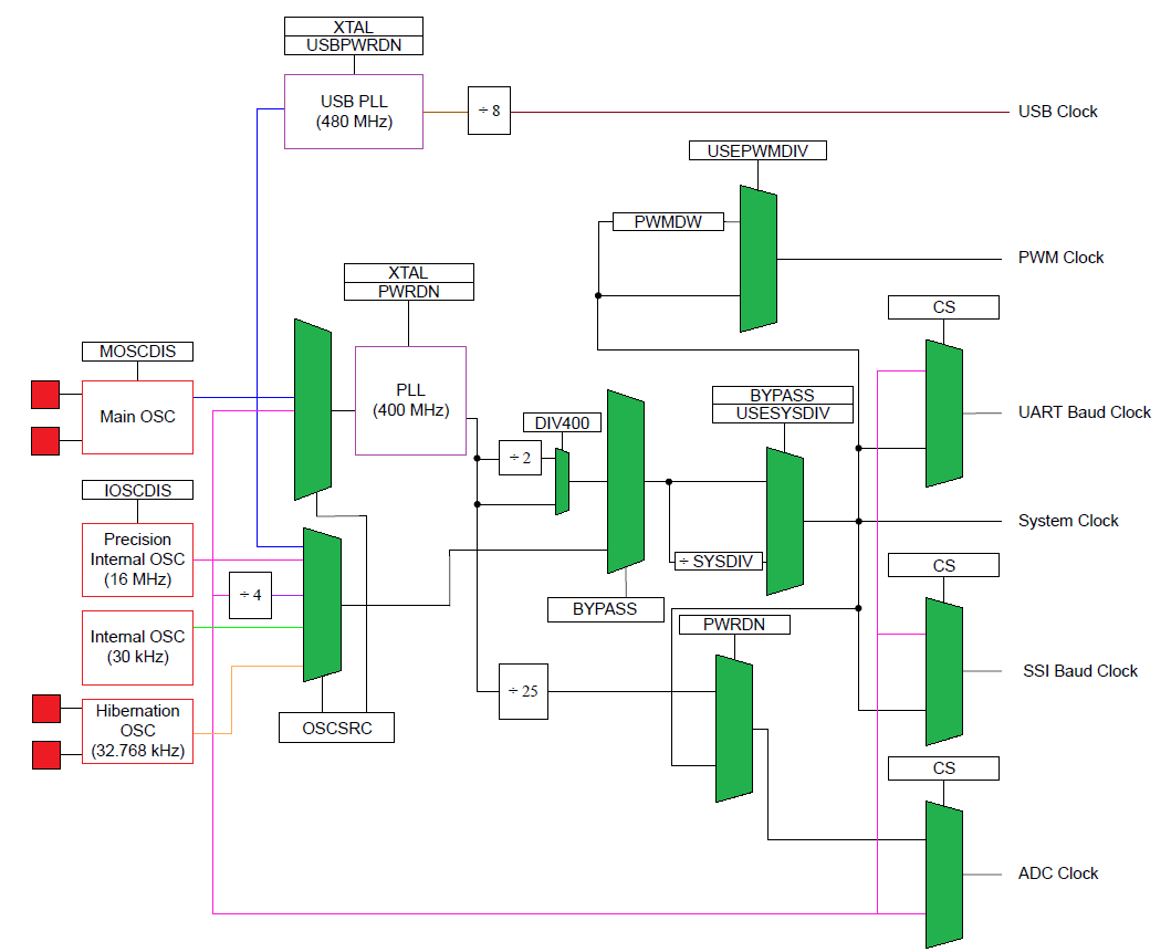
I have taken the liberty to improve the clock tree of Tiva C micros by highlighting special areas of interest. For STM32s micros there is a great tool called STM32CubeMX that can be used to deduce system and peripheral clocks but for Tiva C we have no such tool. We need to do everything on our own and there we are very much likely to make mistakes if we cannot visualize the clock system well. If you notice the clock tree diagram above, it may look a bit complex but in practice it is simple. The green blocks are selectors or multiplexers that are governed by some bit settings. The red boxes are the clock sources. There are four clock sources and two Phase-Lock-Loop (PLL) designated by the purple boxes. The 480 MHz USB PLL is not a concern for now as we will not be discussing about USB communication here. We will be discussing about the 400 MHz PLL only. The interconnections of these sources and blocks make the clock tree appear like a spider web. To resolve this issue I highlighted these connections with different colours. It should be a relaxing view for the eyes now.
Main Oscillator (MOSC)
- Primary external source.
- Can be driven by an external single-ended clock generator or a crystal resonator.
- Only specific frequencies between 4 – 25 MHz are allowed.
- Can be used to drive the internal 400 MHz PLL.
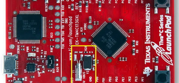
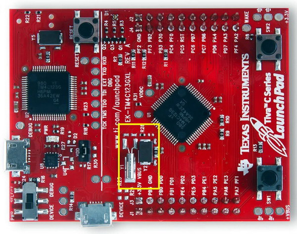
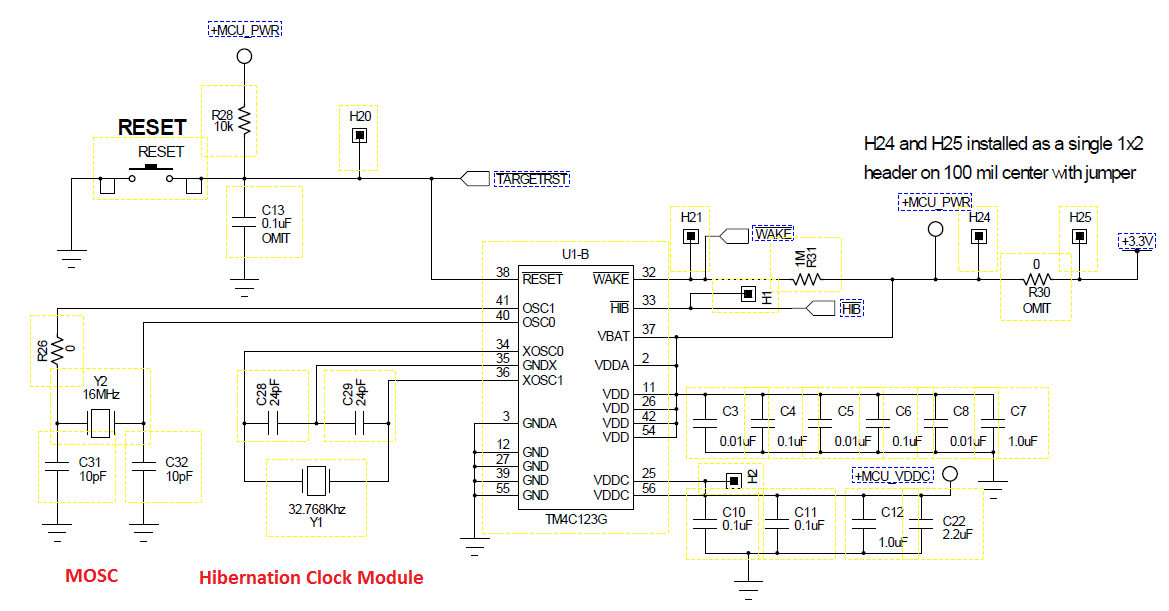
- TM4C123GXL Tiva C Launchpad comes with a 16MHz on board crystal connected to MOSC.
- Needed to clock the 480 MHz USB PLL unit.
Precision Internal Oscillator (PIOSC)
- 16 MHz with 1% accuracy and 3% accuracy over temperature.
- Can be trimmed and calibrated.
- Can be used to drive the internal 400 MHz PLL.
- Can clock internal peripherals like ADC blocks, etc.
Precision Internal Oscillator Divided by 4 (PI4OSC)
- Dependent on PIOSC.
- 4 MHz clock frequency with 1% accuracy.
- Cannot drive the internal 400 MHz PLL.
Low Frequency Internal Oscillator (LFIOSC)
- Typical clock frequency 30 kHz with 50% accuracy.
- Intended for Deep-Sleep power saving modes.
- Can be used when either or both MOSC and PIOSC are powered down.
- Not suitable for accurate time-based operations.
Hibernation Module Clock Source
- Clocked by an external 32.768 kHz RTC crystal or clock generator of same frequency.
- Can provide accurate clock source during Deep-Sleep power saving modes.
- TM4C123GXL Tiva C Launchpad comes with a 32.768 kHz on board RTC crystal.
All of the aforementioned sources can be system clock source. However peripheral clocks can be different. Most peripherals like SSI, UART, ADC, etc. can clocked by the PIOSC unless specified otherwise. PIOSC should never be disabled unless needed and that is because if MOSC is used and it fails for some reason, PIOSC will take over the role of providing clock signal.
400 MHz Phase-Lock-Loop
ARM micros are about speed and power and so most of the times we would want an ARM micro to be as fast as possible. To facilitate this speed thrust most ARM microcontrollers are equipped with Phase-Lock-Loops (PLL). Not only it cuts down cost by removing the need for rare, expensive high frequency external crystals but gives users lot of clock frequency options which would have been impossible otherwise. TM4C123x comes with an internal 400 MHz PLL, the internal working mechanism of which is not important here. However unlike the PLLs of other micros like STM32s, instead of multiplying input clock source, it is divided by System Divisor, Sysdiv to obtain desired clock speeds. No wonder Americans think differently from the rest of the world. With the internal PLL we can generate clock frequencies from 3.125 MHz to 80 MHz, 80 MHz being the top operating clock speed for the TM4C123x. The PLL can be driven by two sources only:
- Precision Internal Oscillator (PIOSC)
- Main Oscillator (MOSC)
Run-Mode Clock Control
The system clock control is provided by a pair of registers called Run-Mode Clock Control, RCC. RCC and RCC2 registers does the following things:
- Selects clock source for sleep and deep-sleep modes.
- Selects whether or not to use the internal 400 MHz PLL.
- Controls the oscillators’ and the PLL’s operating state.
- Set clock divisions and crystal input selection.
The RCC register needs to be configured before RCC2 if RCC2 is needed. RCC2 is basically an extension of the RCC register and it overrides RCC settings. In most cases RCC2 will be needed.
Before going further I would like to reintroduce a very useful tool because what will be discussed next is related to this tool and its use. In several of my earlier posts I mentioned the advantage of using MikroC’s project editor. Using this tool we can easily set the required clock settings.
As seen we can see many drop-down menus. However these may look as much ambiguous as the clock tree itself. Thus we need to look at the three tables shown next. Note the 2s in some menus. These refer to RCC2 while the reset are related to RCC registers.
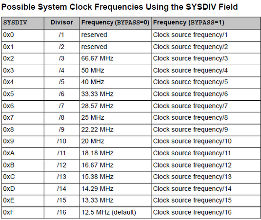
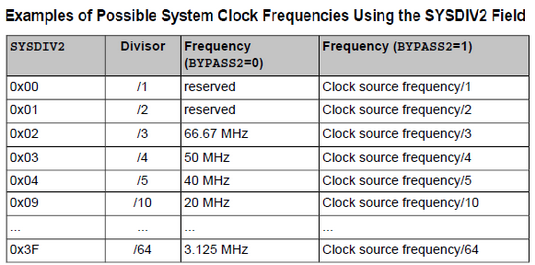
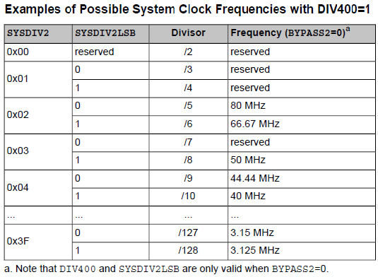
When the BYPASS bit is 0, the internal 400 MHz PLL is used and scaled. It is not bypassed. Likewise when it is 1, preselected clock source is used and scaled accordingly. These tables demonstrate possible clock frequencies.
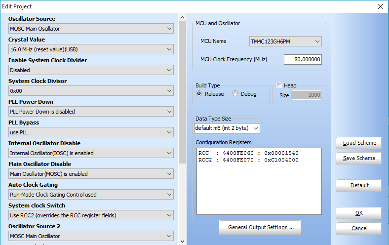
When using the MikroC’s Project Editor, we need to set system clock in a systematic order. Let us consider the 80 MHz max system clock speed setup. First we need to set the RCC settings as shown.
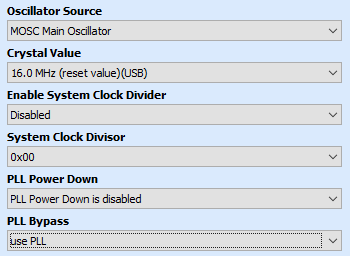
The first two parameters dictate that we will be using the 16 MHz MOSC clock. We selected so because the TM4C123GXL Tiva C Launchpad board comes with an external 16 MHz crystal attached to the MOSC. This clock source is better than the others. We could have used PIOSC as the main clock source but we are keeping it as a backup oscillator. It is also pointless to keep the 16 MHz external crystal unused when it is already embedded in the board. Next we power up the internal PLL and use it. Note we did not use the System Clock Divisor, SYSDIV and that is because we will be using RCC2 also. Though RCC setting will be overridden by RCC2, I advise not to use different settings both registers.
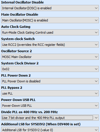
As said earlier, RCC2 is more extensive than RCC. This is reflected by the settings available for RCC2 in the Project Editor. In this section we have to enable/disable the two primary oscillators – PIOSC and MOSC. I am keeping both enabled. PIOSC is the backup should MOSC fail. The next two settings dictate what kind of control we are using to set the system clock and if it is required to use the RCC2 fields. If we do not need to use RCC2, we can simply disable it with the setting available for System Clock Switch. Here we will need it. Since we did not set the PLL completely in the RCC field and we will be using RCC2, we need to set PLL parameters, particularly System Clock Divisor 2, SYSDIV2. I recommend readers to set the last to options as per tables shown previously before setting the PLL. Now our TM4C123 micro is ready to run at 80 MHz system clock.
Please note that right after Power-On Reset (POR), PIOSC starts up before everything else sets up. It should not be a big deal for us. The final outcome from the Project Editor should look like this:
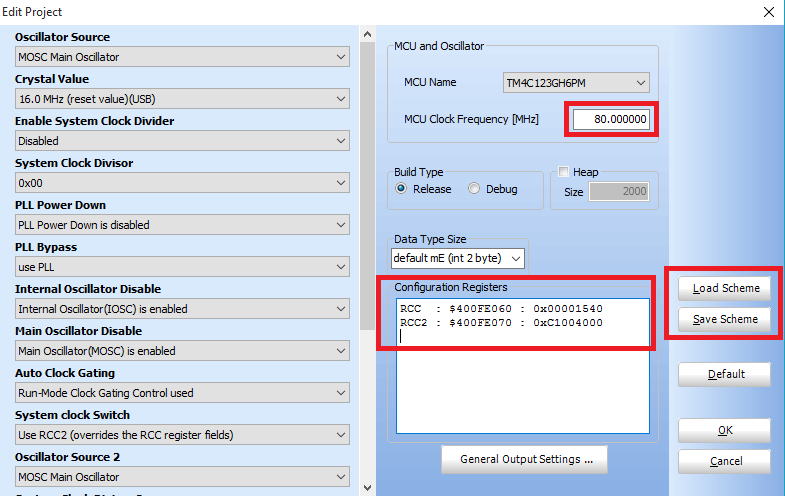
Note the RCC and RCC2 register values. If everything is okay they should look like that. Please take care to set the MCU clock frequency to 80 MHz or otherwise time-related functions like delays and other stuffs may work differently than anticipated. Note that the MCU clock frequency is the system clock frequency and that is why it is so critical. Finally the Project Editor allows us to load and save our favourite system clock schemes – a very handy feature that saves time by quickly loading such schemes.
Software Simulation and Debugging
We have setup the system clock to 80 MHz but we have no quick way to know for sure if it is really working that fast. Here a debugger becomes a must-have tool. All MikroE compilers come with a built-in software simulator or debugger which can assist in debugging codes. Here we will see how helpful it is.
- First create a blank project with TM4C123GH6PM.
- Do not include any library.
- Setup the system clock as per discussion to 80 MHz.
- Write and compile the following piece of code:
void main()
{
Get_Fosc_kHz();
}
The Get_Fosc_kHz built-in function returns the system clock frequency in kHz. If our clock setup is okay, it should be returning 80000, indicating 80 MHz system clock speed.
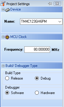
- The Project Settings should be like this:
- Get yourself familiar with options available for the debugger:

- Go to Run >> Start Debugger
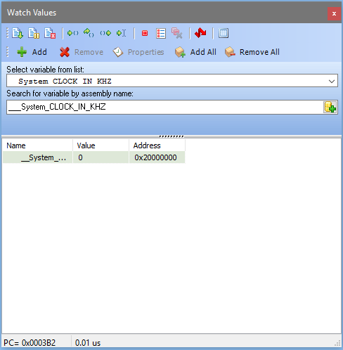
- Go to View >> Debug Windows >> Watch Window
- Select and add as shown:
- Click Step Over. You will notice the following change. Note the value (highlighted in RED) of system clock in KHz.
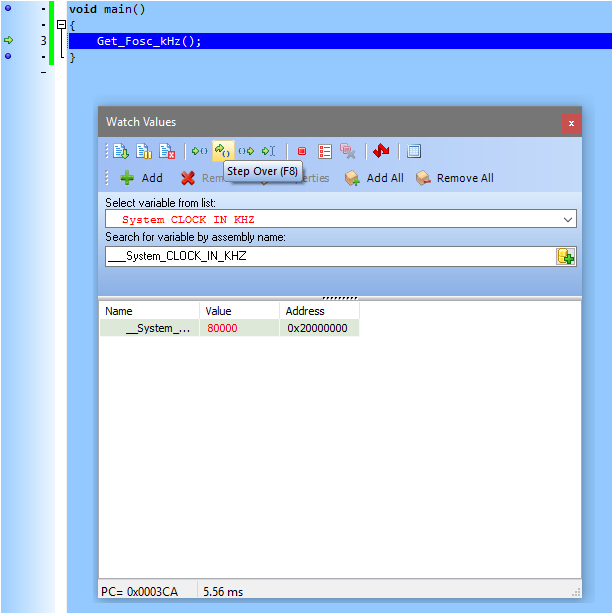
- It is now proved absolutely that our system clock is really working at 80 MHz. You can stop the debugger now.
Check the video for step-by-step details: https://www.youtube.com/watch?v=f7UokGJ7_kI.
Experiment with different clock combinations to build up more confidence on Tiva C clock system. We have yet to do real world experiments and the upcoming post on Tiva C GPIOs will reveal more. We will recheck if this setting of system clock is okay in that post.
Happy coding.
Author: Shawon M. Shahryiar
https://www.facebook.com/groups/microarena
https://www.facebook.com/MicroArena
29.07.2016
*Some images are taken from TI’s websites and datasheet.
|
|