Universal motor driver for PIC16F MCUs
|
|
This application note from Microchip presents the design of an open-loop speed control TRIAC-driven universal motor driver board. An interesting thing about this design is it uses Core Independent Peripheral (CIP) on an 8-bit microcontroller to optimize the processing speed and free up the CPU usage. The complete source code and reference design material are included.

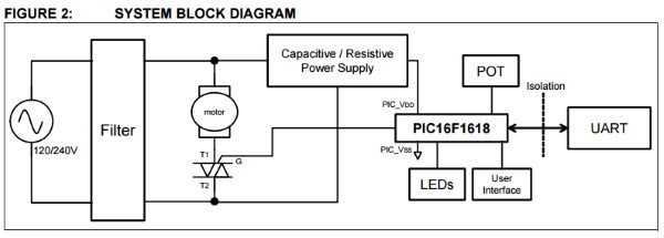
Block diagram of motor controller
The universal motor used in this application note runs from 120V-240V AC power and is driven from a TRIAC. A bench test for running a 220V universal motor has been done. The circuit is powered off the line from an non-isolated AC supply; therefore, safety precautions should be taken when working with this type of system. An isolated on-board UART connection is available for debugging on a live circuit. The low-cost design and its type of motor are suitable for high-torque motor applications commonly used in blenders, food processors, drills and other home appliances.
As shown in Figure 2, the system consists of an AC supply as an input to a passive EMI filter. A selectable capacitive or resistive power supply creates a DC voltage for the microcontroller and its associated input controls. An isolated UART bridge connects to the microcontroller for debug purposes.
A single potentiometer (POT) controls the firing angle of the TRIAC. The Zero-Cross Detection (ZCD) hardware module provides the required synchronization. The TRIAC is pulse driven from multiple pins on the PIC16F1618. A few LEDs indicate the firing angle. A momentary switch toggles the motor ON or OFF.
|
|
Maybe microchip engage in universal motors.
It would be good, the program code to see.