Using Easy Pulse mikro with MPLAB Xpress board
|
|
Easy Pulse mikro is our new educational pulse sensor in a mikroBus form factor. Like our previous Easy Pulse sensors (Easy Pulse and Easy Pulse Plugin), it is also based on the principle of transmittance photoplethysmography (PPG) applied to a fingertip. The sensor consists of a pair of IR LED and photodiode to detect the cardiovascular pulse signal from the fingertip. The output of the sensor is passed through a necessary instrumentation amplifier to derive a nice and clean analog PPG waveform. The analog output is routed to the AN pin of the mikroBus connector. In this article, I will describe how to use the Easy Pulse mikro sensor with Microchip’s latest MPLAB Xpress development board for uniform ADC sampling of the analog PPG signal and sending the samples to a PC for post digital processing in order to retrieve the heart-beat rate. Currently, you can buy this sensor from our Tindie Store in United States and Elecrow Store in China.
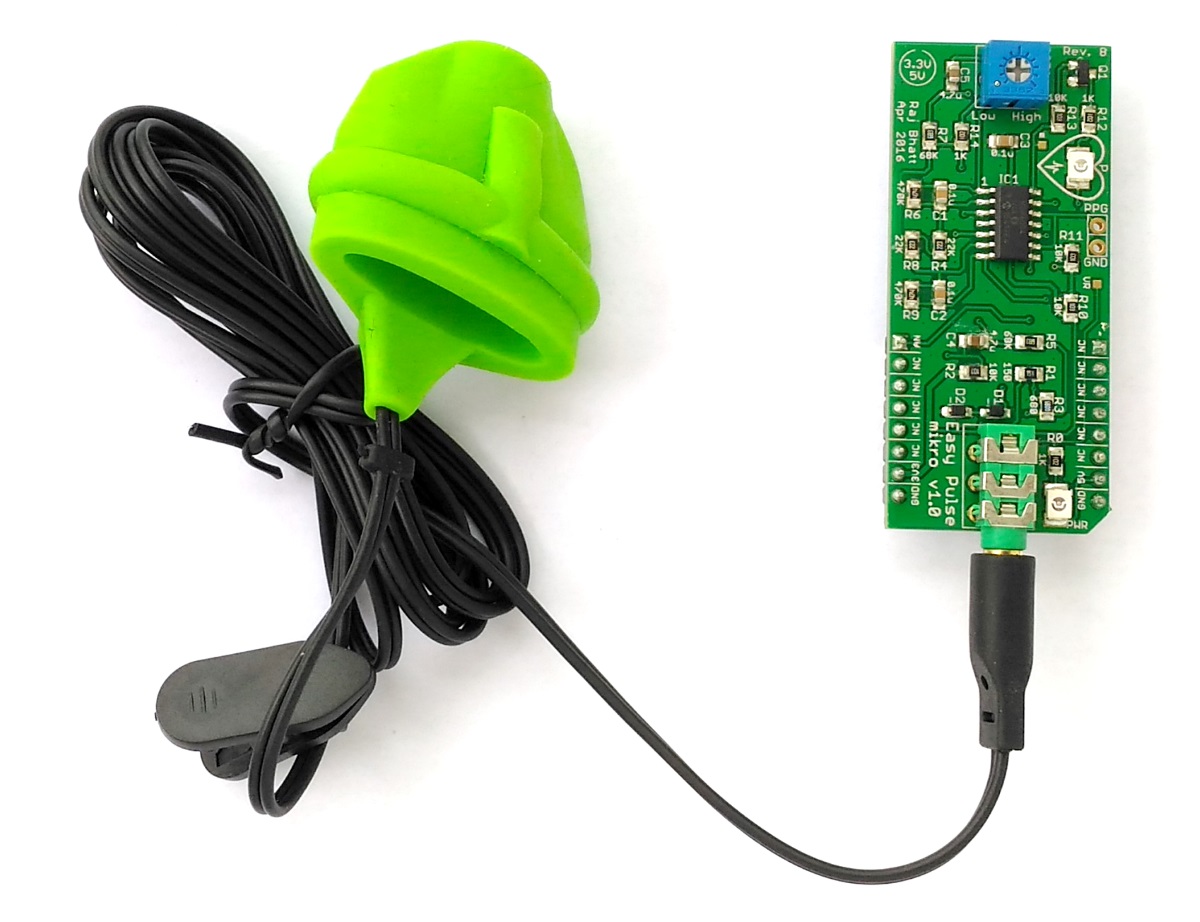
Easy Pulse mikro
The following figure highlights the basic features of the Easy Pulse mikro instrumentation board. For more details, read the documentation page.
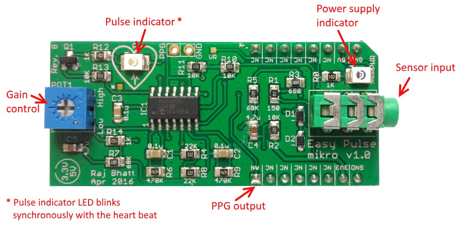
Easy Pulse mikro features
MPLAB Xpress Board
In this section, I will provide a brief overview of MPLAB Xpress board and its features.
Features
The MPLAB Xpress Evaluation Board features PIC16F18855, an 8-bit PIC processor with Core Independent Peripherals (CIPs) combined with eXtreme Low Power (XLP) technology suitable for a wide range of general purpose and low-power applications. CIPs in PIC MCUs, once initialized, can handle their tasks with zero intervention from the core (or CPU), thereby simplifying the design of embedded systems. During CIP operations, the CPU is free to perform other system tasks, if available, or can be idled and put into sleep mode to save system power. For the details of the available CIPs on PIC16F18855, refer the datasheet. The PIC16F18855 features 14 KB of program memory, 1024 bytes of RAM, and a configurable (up to 32MHz) internal oscillator. The I/O pins are brought to two rows of blank headers (0.1″ pitch) on opposite edges of the board. There are four red LEDs (with current limiting resistors) connected to I/O pins RA0 through RA3 and the EMC1001 I2C temperature sensor pre-installed on the board. A 10K potentiometer is also available (potentiometer output goes to RA4/ANA4 pin) for a quick analog-to-digital conversion demo. The availability of a mikroBus socket on board allows a simple Plug-and-Play solution for connecting mikroElektronika’s accessory boards (called Click Boards) that would greatly enhance the capability of MPLAB Xpress board.
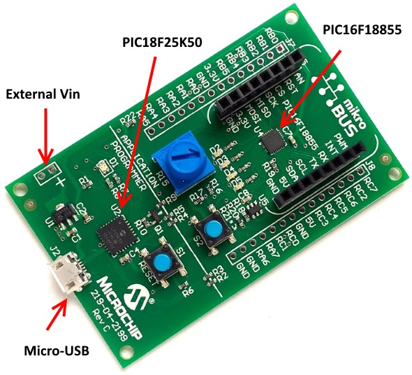
MPLAB Xpress Evaluation Board
On-board Programmer
The MPLAB Xpress board also carries an onboard programmer using the PIC1825K50 microcontroller that emulates as a USB storage device, thereby offering a driver-free plug and play USB interface. The HEX file can be uploaded to the target PIC16F18855 MCU through a simple drag and drop operation.
Power supply
The MPLAB Xpress board is receives a 5V power supply through the micro USB connector. There is a 3.3V regulator circuit on-board to provide VCC supply to both PIC MCUs. The un-regulated 5V from the USB port and the regulated 3.3V output are also accessible at the blank headers and the mikroBus socket pins. The board also allows an external power supply (VIN) that goes to the input of the 3.3V regulator circuit. Because there is no 5V regulator on board, the VIN supply goes directly to all the pins that are marked as 5V. So you should be careful in case you would like to power the Xpress board with an external power source. Make sure VIN is a regulated +5V.
Thanks to Jason Wellman from Microchip for providing a free sample of MPLAB Xpress board.
Experimental Setup
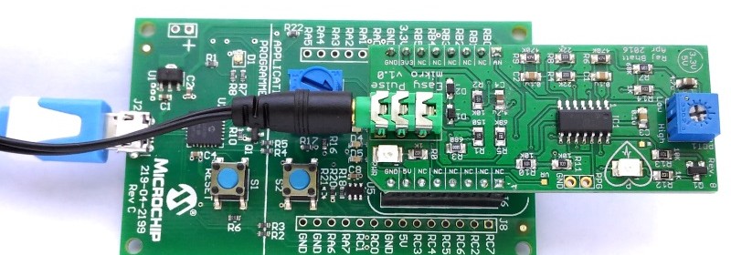
For this experiment, the Easy Pulse mikro is inserted into the mikroBus socket on the Xpress board as shown below. Make sure that the AN pin on the sensor board plugs into the AN pin of the mikroBus socket on the Xpress board. The potentiometer on the sensor board controls the gain of the instrumentation amplifier and can be adjusted to somewhere close to the middle position.
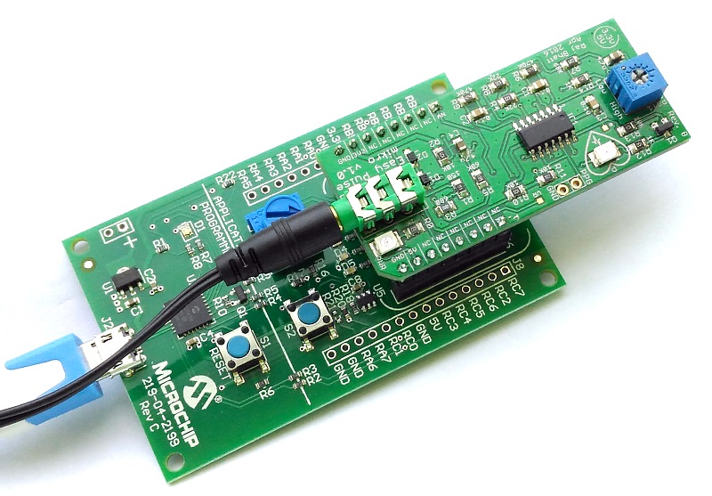
Experimental setup
Software
The PIC16F18855 MCU on the MPLAB Xpress board is programmed to acquire 10-bit ADC samples of the PPG signal. The sampling is done at a uniform rate of 1 sample per 5 millisecond. The ADC samples are then sent to the host PC through the USB connection. The PIC16F18855 sends the ADC samples over its EUSART peripheral to the PIC18LF25K50, which is configured to operate as a CDC USB device to translate the EUSART message for transmission over the USB protocol to a host computer serial COM Port. You can find more details about Serial Communication using MPLAB Xpress Board Microchip Wiki page. A PC application was developed using Processing language to receive the ADC samples from the COM port and process the data for extracting the heart beat rate. The firmware for PIC16F18855 is written and compiled using Great Cow BASIC, which is an open-source BASIC compiler for PIC and AVR microcontrollers. The key challenge was to achieve a precise 5 milliseconds sampling interval. Using a built-in Delay function between ADC sampling is not recommended because that is not accurate enough for this project. Besides, the finite time involved in EUSART communication must also be considered for precise timing of 5 millisecond interval between samplings.
This project achieves accurate 5 millisecond duration using the Timer0 module built inside the PIC16F18855. The Timer0 module can operate as either an 8-bit timer/counter or a 16-bit timer/counter. The mode of operation is selected with the T016BIT bit of the T0CON register. Here, it is used as an 8-bit timer. The Timer0 output consists of 8-bit TMR0H and 8-bit TMR0L registers. It is interesting that in 8-bit mode, the Timer0 interrupt flag bit (TMR0IF) is set when the 8-bit TMR0L matches the TMR0H value. This is different than the operation of Timer0 module in mid-range 8-bit PIC MCUs, where the TMR0 register is only 8-bit and the Timer0 interrupt flag is set every time the TMR0 register overflows. I have also covered Timer0 topic before in Lab 7: PIC Timers article. The operation of Timer0 in PIC16F18855 puzzled me for a while. Many thanks to Evan Venn from Great Cow BASIC for explaining to me the secrets of Timer0 inside PIC16F18855. You can find his explanation at this Tumblr post.
My BASIC code goes like the following:
1 2 3 4 5 6 7 8 9 10 11 12 13 14 15 16 17 18 19 20 21 22 23 24 25 26 27 28 29 30 31 32 33 34 35 36 37 38 39 40 41 42 43 44 | 'Chip Settings. #chip 16f18855,32 #Config FEXTOSC_OFF, RSTOSC_HFINT32 #Config WRT_OFF, CPD_ON, MCLRE_ON 'Set the PPS of the PWM and the RS232 ports. UNLOCKPPS RC0PPS = 0x0010 'RC0->EUSART:TX; RXPPS = 0x0011 'RC1->EUSART:RX; LOCKPPS 'Setup the timer. 'params Source, Prescaler , Postscaler InitTimer0 Osc, PRE0_4096 + TMR0_HFINTOSC, POST0_1 ' Here source is selected to be internal oscillator. ' Timer0 input clock is 32MHz followed by a 4096 prescaler ' So, the actual clock frequency of Timer0 input is 32000000/4096 ' = 7812.5 Hz. Time period = 1/7812.5=0.128 milliseconds ' Now, 5 ms duration = 5/0.128=39 (or 0x27) clock pulses. ' Start the Timer by writing to TMR0ON bit StartTimer 0 ' Set the Timer start value TMR0H =0x26 and TMR0L=00 ' Timer0 interrupt occurs when 8-bit TMR0L matches the TMR0H value ' That will occur on the arrival of 39th pulse. This will give ' a precise 5ms duration for ADC sampling. SetTimer ( 0, 0x2600 ) #define USART_BAUD_RATE 115200 #define USART_TX_BLOCKING dir portb.0 in dim adc_value as Integer do wait while TMR0IF = 0 ' Clearing IF flag. TMR0IF = 0 'Set timer to 5ms before the next event occurs. SetTimer ( 0, 0x2600 ) adc_value = readAD10(AN8) hserprint adc_value HSerSend 10 loop |
The comments explain the settings for Timer0. The 32MHz internal clock is selected as source for the Timer0 input. It is prescaled to 1/4096 to convert it to a 7812.5 Hz clock, which has a time duration of 0.128 milliseconds. A 5 ms duration is achieved in 5/0.128=39 clock pulses.
Download Great Cow BASIC program
The PC application is developed using Processing. It uses Andreas Schlegel’s controlP5 libraries for graphical interface. When you connect the MPLAB Xpress Board to PC with an USB cable, it will appear as a COM port. The Processing app allows you to chose the right COM port from a drop-down list, as shown below.
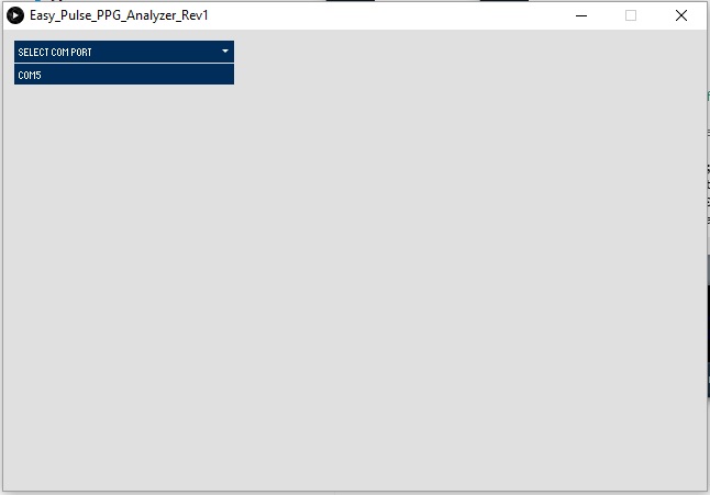
Select right COM port your MPLAB board is connected to
After you click on the COM port, the App is connected to it and starts receiving the ADC samples from the board. The App receives 1000 samples and processes to compute the heart beat rate. The algorithm for computing heart beat rate from PPG peaks is described in my PC based heart rate meter project. The program detects four consecutive peaks and computes the time differences between peaks to derive heart beat rate in beats per minute (BPM). The computed heart beat rate and PPG waveform are displayed on the screen.
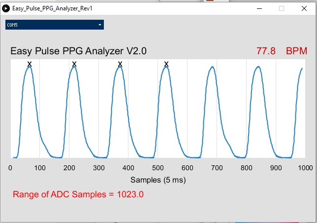
PPG waveform and heart beat rate in BPM

MPLAB Xpress board sends ADC samples to PC over USB-UART bridge
Download Easy_pulse_ppg_analyzer_rev1 Processing code
Buy Easy Pulse mikro from our Chinese store
Buy Easy Pulse mikro from our US store
Conclusion
A PC-based PPG analyzer project using MPLAB Xpress Board and Easy Pulse mikro sensor was discussed in this article. The PPG waveform from the sensor board was digitized by the Xpress board and the ADC samples were sent to a host PC through a USB-UART bridge. A Processing-based PC App was also developed to process the ADC data samples to re-construct the PPG waveform. The heart beat rate was computed from the identification of peaks of PPG waveform and the temporal separation between the peaks.
|
|
how will I get this product in India ?
You can order online from Elecrow.