Development board for PIC16F1938
|
|
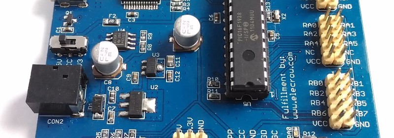
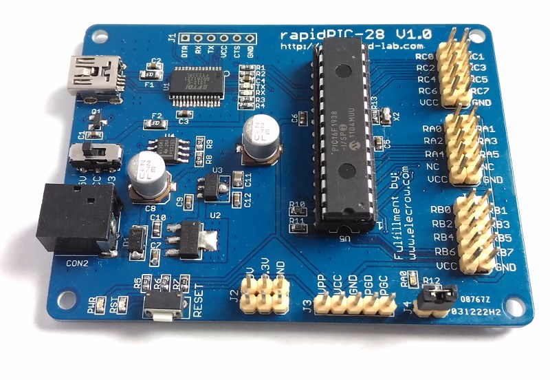
The PIC16F1938 is a versatile 28-pin MCU belonging to Microchip’s extreme low power microcontroller family featuring nanoWatt XLP technology, 28KB of programming memory, 1KB of RAM, 11 ADC channels, and tons of other peripherals. A while ago, I designed a development board for this MCU and I thought it would be worth sharing this design here. The development board features an onboard USB-UART bridge to support the ds30 Loader for easy programming of the PIC MCU. All I/O pins are accessible through 2×5 headers.
PIC16F1938 development board
Summary of Features:
- On-board 5V and 3.3V regulators
- Support both 5V and 3.3V MCUs. The power supply option is selected through a slide switch (SW1).
- FT232RL USB-UART bridge
- PIC16F1938 runs at 16 MHz external resonator
- PIC is preloaded with the ds30 Loader (bootloader)
- All I/O pins are accessible through 2×5 male headers. Each header connector has VCC and GND pins.
- ICSP connector for PICKit2 or 3
- On-board LED connected to RA0 pin.
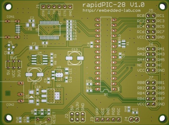
Top layer of PCB
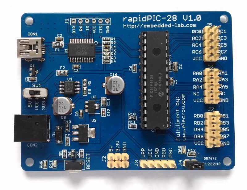
Assembled PIC16F1938 development board
Download ds30Loader Bootloader for PIC16F1938
The pre-compiled HEX file for bootloader can be found inside the dist folder.
Following is the list of components used in this development board.
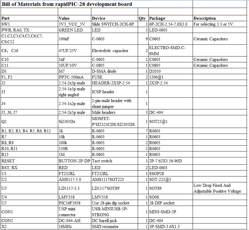
BOM
|
|
Pingback: Development board for PIC16F1938 - Electronics-Lab