How to measure capacitance with a microcontroller?
|
|
Microcontrollers are widely used in measuring various physical variables. The techniques involved in the measurements could be different for individual variable type and are mostly based on the characteristics of the variables to be measured. This tutorial describes some methods for measuring the capacitance of a capacitor using microcontrollers. The techniques use the characteristics of the capacitor itself and are therefore universal and can be easily implemented with any microcontrollers.
Based on R-C time constant
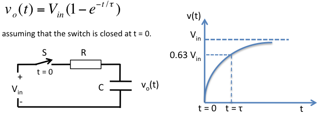
We know that the voltage across a capacitor doesn’t build instantaneously. The charging and discharging of a capacitor take place exponentially, and depends upon the resistance it is connected to. When a capacitor (C) is charged from a source voltage (Vin) through a series resistor (R), the instantaneous voltage across the capacitor is given by,

Here, ? = RxC, is known as the time constant. If you put t = ? in the above equation, you get
vo(t = RC) = 0.63 Vin.
Thus at t = RC, the voltage across the capacitor reaches at about 63 % of the supply voltage.
Now, if you could somehow measure the time elapsed before the voltage across the capacitor reaches 63 % of the supply voltage, you can easily find the capacitance value, assuming the resistance R is known. The measurement of time interval can be done by using the built-in Timer module of a microcontroller. You need to tell the microcontroller when to start and when to stop the Timer. The timer should be started right after the switch S is closed and must be stopped when the capacitor voltage reaches 0.63 Vin. Modern microcontrollers are equipped with one or more analog comparator modules. You can set the reference pin of the comparator to 0.63 Vin using a potentiometer, and feed the another input of the comparator with the voltage across the capacitor. When the capacitor voltage crosses 0.63 Vin, the comparator output is flipped, which can interrupt the microcontroller to stop the timer. Noppharat Tawanron has demonstrated this technique with PIC microcontroller in his website.
Based on an oscillation circuit
A capacitance is a primary component in determining the frequency of many oscillation circuits such as an astable multivibrator using a 555 timer IC. The frequency of oscillation for the 555 timer circuit shown below is given by,

Assume R1 = R2 = 10K, you get C = 48000/f, where f is in Hz and C is in nF. In this way, the capacitance can be estimated indirectly by measuring the frequency of the 555 output. You can create a 10 ms window in the software and count the number of output pulses within that window using the Timer module (operated as a counter). Suppose, if N pulses are arrived in the 10 ms window, then C = 480/N, nF. If you get N= 48, the measured capacitance would be 10 nF.
Remember that both of these methods rely on the accuracy of the resistance values used.
|
|
Do you know any arduino program for the oscillation circuit?
thank u