Arduino Projects
Arduino needs no introduction. It is an easy-to-use, yet powerful, open-source embedded system development platform that has gained huge amount of popularity in past few years, specially among hobbyists. The standard hardware consists of an 8-bit Atmel AVR processor with on-board headers providing access to its I/O pins. The processor is pre-programmed with a serial bootloader that simplifies the uploading of user programs to the on-chip flash memory without the need of any external programmer. Because of its low cost, user-friendly software development environment (open-source C/C++ like programming platform), rich set of libraries, and tons of resources available online, Arduino has become a common choice for electronics hobbyists these days. Here, I have listed some of the Arduino projects that I built and I hope some of you will find them as good learning resources on Arduino.
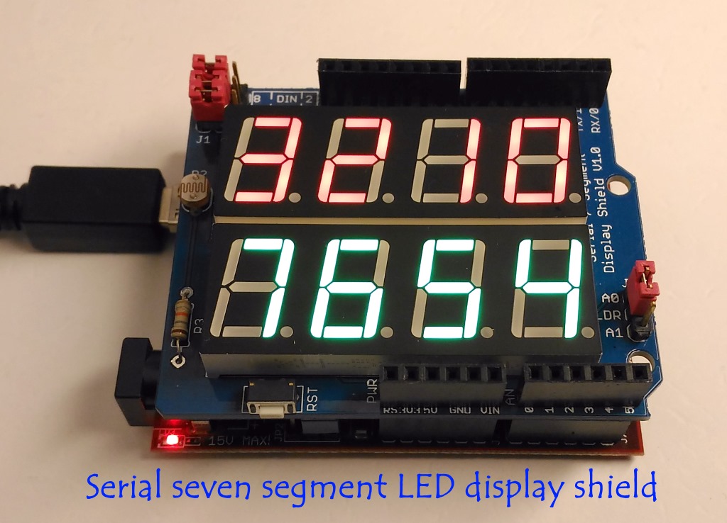
This project describes a serial seven segment LED display shield for Arduino Uno or compatible boards. The shield consists of eight 0.56″ seven segment displays that are driven by one MAX7219 chip. The shield also features a light dependent resistor (LDR) to implement adaptive brightness control to the LED displays. The LDR output can be fed to A0 or A1 analog input channel of Arduino to read the surrounding illumination level. Arduino can then use that information to adjust the brightness of the LED displays. A demo code and Eagle CAD files are also provided in the latter part of the article.
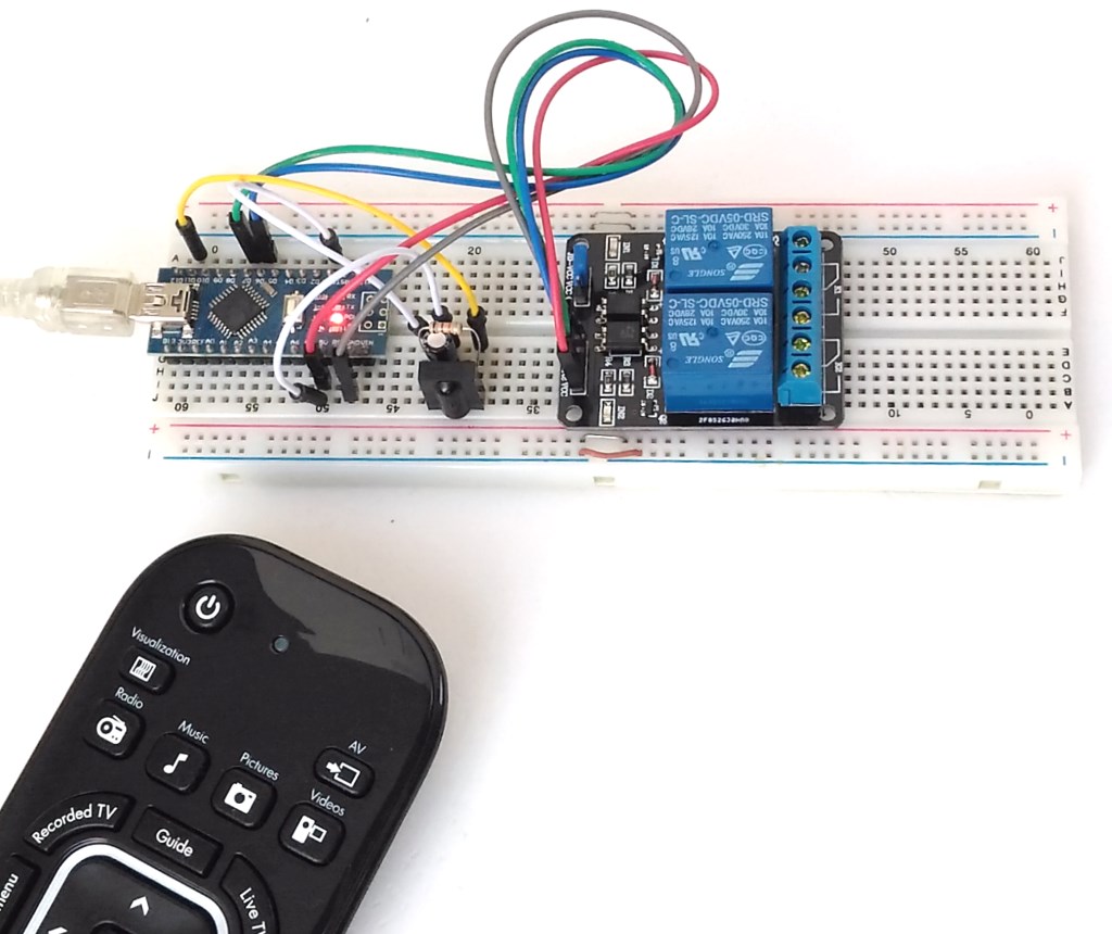
This project describes how to make an Arduino-based IR receiver for decoding the IR signals coming from a TV/DVD remote. Based on the decoded values corresponding to specific buttons on the remote, the Arduino is programmed to control multiple relay switches.
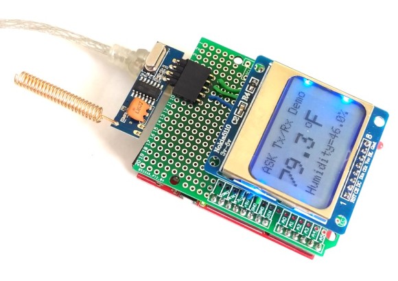
This Arduino project explores an easy wireless communication setup between two Arduinos using low-cost ASK RF transmitter and receiver modules that are readily available in the market. They are found in different shapes, but functionally they are all same. Both Tx and Rx modules contain a single data line for input and output and support a low-speed Amplitude Shift Keying modulation for data communication.
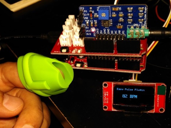
Arduino Crowtail is a modular and ready-to-use building block set from Elecrow for rapid prototyping with Arduino. It consists of a base Arduino Uno shield to which various sensor and I/O modules can be conveniently interfaced through standardized connectors. In this example, I am going to illustrate how to use the Easy Pulse Plugin sensor with a Crowtail base shield and a Crowtail OLED module to make a stand-alone pulse meter.
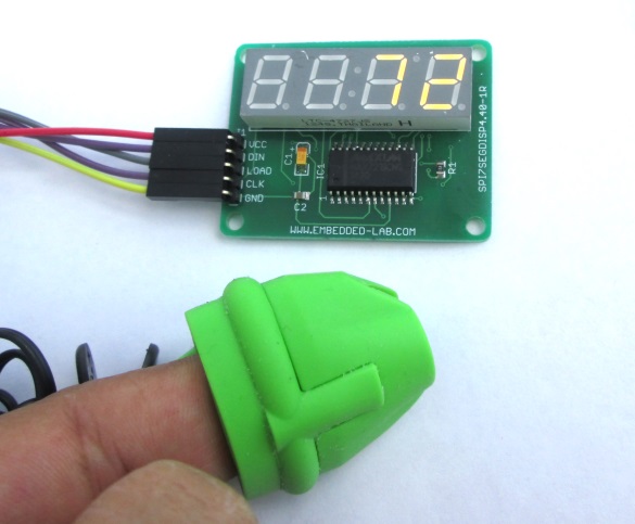
The Arduino heart rate meter will use Arduino Uno, Easy Pulse Plugin, and 4-digit SPI seven segment LED display module. It computes the heart beat rate by processing the analog pulse signal output from the Easy Pulse Plugin sensor and displays it on the seven segment display module. The heart beat rate is refreshed every ~3 sec.
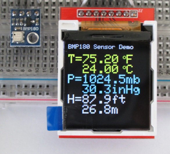
The BMP180 is a new generation digital barometric pressure and temperature sensor from Bosch Sensortec. In this Arduino project, we will briefly review this device and describe how to interface it with an Arduino Uno board for measuring the surrounding temperature and pressure. We will also discuss about retrieving the sensor altitude from its pressure readings.
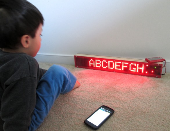
LED matrix displays are great fun. They are visually charming, and readable from a far viewing distance with a much wider angle of view as compared to many other types of electronics displays. They can display all kinds of information, including text, graphics, and animation. This is one of my favorite Arduino projects and is about making a portable Bluetooth-controlled 8×64 monochromatic LED matrix (total 512 LEDs) for displaying scrolling text message.
Pages: 1 2
Have done building the template from Whatimade after some change it runs.
http://www.whatimade.today/programming-an-8-digit-7-segment-display-the-easy-way-using-a-max7219/
Only drawback with the Raj-display, they light up ALL segment FULL brightnes on power up.
This sucks much current!
This happens all the time you power up the circuitry, regardless of having placed the Iset-resistor or having set the brightness register to “1”.
Please, read the notes regarding placing and modifying the rinkydinky libraries carefully.
The code (Fahrenheit portion removed):
/**
* Display (Date) Time Temperatur on 2*4 Max7219 Raj LED-Display
* used those with the Max7219 SMD SO chip soldered on
*
*
* RTC DS3231 (read the clock and temp sensor)
*
*
* Rinkydinky “DS3231” and “HW_AVR” libraries used
* Copy both the DS3231-library files AND the HW-Library files into the same DS3231-folder!
* They have to be placed manually to the library folder structure.
* Remove the hardcoded links /avr/hardware/… from both files HW_AVR_defines.h and HW_AVR.h !
* Let the library manager scan and by doing this way rebuilding the datase of installed libraries!
* In case the compiler mocks about having found many DS3231 libraries, move those unwanted libraries *temporarily out of the libry folder!
* Let the library manager scan and rebuilding the datase of installed libraries again!
* Let the IDE “correct and reload the code”.
* Thereafter I have successfully compiled on Arduino IDE 1.6.5
*
* @file max7219_DS3231_temp_clock.ino
*
* @brief view DATE/TIME/TEMPERATURE using an 8-digit
* 7-Segment display
*
* @history Feb 6th, 2017
*
*
* @author Allan Schwartz
* Michael Diamond
*
* @maker/editor April 7th 2019 changed for using Raj 2*4 digit I2C Max7219 LED display
*
*
* @notes The following Arduino Pins are attached:
*
* name Arduino 7 Segment display
* —– —- —–
* +5V VCC
* GND GND
* DIN D10/MOSI DIN
* CS D11/SS Load/CS
* CLK D12/SCK CLK
*
* name Arduino RTC module
* —– —- —–
* nc 32K
* nc SQW
* SCL SCL/A5 SCL
* SDA SDA/A4 SDA
* 5V VCC
* GND GND
*/
#include // import library from rinkydink.com
// define pins attached to MAX7219 (and also see notes above)
#define MAX7219_DIN 10
#define MAX7219_CS 11
#define MAX7219_CLK 12
enum { MAX7219_REG_DECODE = 0x09,
MAX7219_REG_INTENSITY = 0x01,
MAX7219_REG_SCANLIMIT = 0x0B,
MAX7219_REG_SHUTDOWN = 0x0C,
MAX7219_REG_DISPTEST = 0x0F };
enum { OFF = 0,
ON = 1 };
const byte DP = 0b10000000;
const byte C = 0b01001110;
const byte c = 0b00001101;
DS3231 rtc(SDA, SCL);
void setup()
{
// Serial.begin(115000); // initialize serial communication
// Serial.println(“max7219_7segment_date_time_temp”);
// define type of pin
pinMode(MAX7219_DIN, OUTPUT); // serial data-in
pinMode(MAX7219_CS, OUTPUT); // chip-select, active low
pinMode(MAX7219_CLK, OUTPUT); // serial clock
digitalWrite(MAX7219_CS, HIGH);
resetDisplay(); // reset the MAX2719 display
rtc.begin(); // init. the DS3231 RTC interface
// Uncomment the following lines to set the RTC initally ONLY!
// nur zum Stellen der RTC ( mit Batterie) einmalig aktivieren
//rtc.setDOW(WEDNESDAY); // Set Day-of-Week to WEDNESDAY
//rtc.setTime(3, 40, 0); // Set the time to 4:20pm
//rtc.setDate(7, 4, 2019); // Set the date, adjust this to the time you compile and send the code over!
}
void loop()
{
String str;
// … display Date, dd.mm.yyyy
// read the date as a string from the RTC
// str = rtc.getDateStr(FORMAT_LONG);
// Serial.println(str); // debug
// displayDate(str); // display on the 7-segment
// delay(5000);
// show the time for 10 seconds, then the temperature
// … display Time: hh-mm-ss
for ( int i = 0; i < 9; i++ ) //adjust i to the amount of repeated cycles you want
{
// read the time as a string from the RTC
str = rtc.getTimeStr(FORMAT_LONG);
// Serial.println(str); // debug
displayTime(str); // display on the 7-segment
delay(1000);
}
{ // display temp in lower row
String str;
float t = rtc.getTemp();
str = String(t, 2); // format that value
Serial.println(str); // debug
displayTemp(str,c); // display on the 7-segment
delay(3000); //adjust i to the display time you want
}
} // End loop
//—– Sub routines —–
void displayTemp(String tempString, char c ) // display the temp on the lower row Centi grade value followed by a small chracter "c"
{
set_register(MAX7219_REG_SHUTDOWN, OFF); // turn off display
set_register(MAX7219_REG_SCANLIMIT, 7); // scan limit 8 digits
// decode the 3 mostsignificant Temp-digits ONLY, use the following data for control only
// have the temp output shortended to 3 digits only see the three "1" register bits below
set_register(MAX7219_REG_DECODE, 0b11100000);
//set_register(8,0); //0=Blindschalten
//set_register(8,1); 1="1"
//set_register(8,2); 2="-"
//set_register(8,DP); DP on
// Temp-Bits: 0(Zehner), 1(Einer), 2=Doppelpunkt ignorieren, 3(Zehntel), 4(Hundertstel) ignorieren
set_register(1,0);
set_register(2,0);
set_register(3,0);
set_register(4,0);
set_register(5,c);
set_register(6, tempString.charAt(3));
set_register(7, tempString.charAt(1)| DP); //DP aktivieren
set_register(8, tempString.charAt(0)); // ganz links
set_register(MAX7219_REG_SHUTDOWN, ON); // Turn On display
}
//——————-
void set_register(byte reg, byte value)
{
digitalWrite(MAX7219_CS, LOW);
shiftOut(MAX7219_DIN, MAX7219_CLK, MSBFIRST, reg);
shiftOut(MAX7219_DIN, MAX7219_CLK, MSBFIRST, value);
digitalWrite(MAX7219_CS, HIGH);
}
//——————-
void resetDisplay()
{
set_register(MAX7219_REG_SHUTDOWN, OFF); // turn off display
set_register(MAX7219_REG_DISPTEST, OFF); // turn off test mode
set_register(MAX7219_REG_INTENSITY, 0x01); // display intensity
}
// … display the DATE on the 7-segment display
void displayDate(String dateString)
{
set_register(MAX7219_REG_SHUTDOWN, OFF); // turn off display
set_register(MAX7219_REG_SCANLIMIT, 7); // scan limit 8 digits
set_register(MAX7219_REG_DECODE, 0b11111111); // decode all digits
set_register(1, dateString.charAt(4)| DP); // plus decimal point
set_register(2, dateString.charAt(3));
set_register(3, dateString.charAt(1)| DP);
set_register(4, dateString.charAt(0));
set_register(5, dateString.charAt(9));
set_register(6, dateString.charAt(8));
set_register(7, dateString.charAt(7));
set_register(8, dateString.charAt(6));
set_register(MAX7219_REG_SHUTDOWN, ON); // Turn on display
}
// display the time (hours, minutes) on the top row
// display the seconds on the second row
void displayTime(String timeString)
{
set_register(MAX7219_REG_SHUTDOWN, OFF); // turn off display
set_register(MAX7219_REG_SCANLIMIT, 5); // scan limit 6 digits
// reserve 6 digits (1-6) for the temp-Data,
// those with "0" (digit 7,8) are reserved for control data i.e. blank the digit by sending "0"
set_register(MAX7219_REG_DECODE, 0b00111111);
// Time-Bit 0,1, 2=Doppelpunkt ignore, 3,4, 5=Doppelpunkt ignore, 6,7 control data
set_register(1, timeString.charAt(4)| DP);
set_register(2, timeString.charAt(3));
set_register(3, timeString.charAt(1)| DP);
set_register(4, timeString.charAt(0));
set_register(5, timeString.charAt(7));
set_register(6, timeString.charAt(6));
set_register(MAX7219_REG_SHUTDOWN, ON); // Turn on display
}
Hi Raj,
By accident I have found out the reason why it does not work properly together with the Arduino and RTC-chip.
Have all placed on a big breadbord with a lot of smoothing capacitors and some filtering resistors in series with Vcc.
The LED module with the Max7219 must be considert being a RF-transmitter.
When touching the metal plate underneath the breadboard it works as it should.
Obviously this is the same story when I had it attached to the DIY PIC-controller board.
I’m not an Radio amateur.
But I know this is exactly the effect when making a capacitive counterwight to an antenna or operating high resistive high impedance amplifiers (tube or MOSFET) I made earlier.
Touchsensitive device long before the stupidly small touchscreen phones came up.
Cheers
hey I want your help on arduino based program, to make automatic autoclave I need it with simulation.
Hi – I’m an 82 YO senior citizen and I’m trying to learn and build a phone interface using an Arduino R3. I have no previous software or embedded systems experience and would like to build a prototype of this phone interface. Which system would be best for me to get this project headed in the right direction.
Thank you.
Stan Simon
ssimon333@hotmail.com
David A. Mellis built one before, you can acess the page for more information.
http://alumni.media.mit.edu/~mellis/cellphone/
Is there a tutorial for connecting an Arduino Uno to a Nokia 5110?
Most tutorials (including yours) use either a different Arduino to connect to the Nokia or a different LCD to connect to the Arduino Uno. .
Thanks.
do you have any example for Bmp180 sensor using a Graphic Display LCD?
i request the source codes for blood glucose based micro controller pic18f4520 circuit which use Gsm modem to send sms to the mobile phone.
“I request the source codes”
Wow !
Your majesty couldn’t just kindly ask, with a please ???