Getting ready for the first lab
|
|
This is to be followed after you have successfully completed the following steps:
- Installed mikroC Pro for PIC on your PC.
- Installed the programmer software that came with your PIC programmer. If you have got an iCP01 USB PIC programmer from iCircuit Technologies, you should install Microchip’s PICkit programming software.
- Got a breadboard and a regulated +5V power source.
Basic setup on the breadboard
As mentioned before all the experimental circuits will be constructed on the breadboard because it is easy to modify the circuit and correct any wiring error. Figure 1 shows the pin diagrams of PIC16F688. It is a 14-pin microcontroller with a precision internal oscillator. It provides 12 I/O pins with individual direction control, and can drive LEDs directly. 8 out of 12 I/O pins also serve as ADC channels for the internal 10-bit ADC. The various features of PIC16F688 will be discussed later in more detail in following lab sessions. For now, we will look at a simple circuit setup for PIC16F688 on the breadboard that will be used in all the experiments.

Figure 1: PIC16F688 pin diagram
 Figure 2: Basic setup for PIC16F688 with an external reset switch
Figure 2 shows a PIC16F688 microcontroller with minimum support components. We will use the built-in oscillator of PIC16F688 so that we don’t have to provide an external oscillator circuit. This frees up two port pins (2 and 3) that can be used for I/O purpose.
There are many circumstances when you may want to reset the microcontroller and force the program execution to restart from the beginning. This can be achieved by connecting an external reset button to the MCLR (Master Clear) pin of PIC16F688 as shown in Figure 2. Normally, the MCLR pin is at logic 1, and it goes to logic 0 when the reset button is pressed. The logic 0 at MCLR pin resets PIC16F688. When the button is released, the microcontroller operates normally, executing instructions from the beginning of the program memory. However, the MCLR pin can also be disabled and used just as an I/O pin through software (will see it later).
PIC16F688 can be programmed serially (while in the target circuit) through two pins: ICSPDAT (RA0, 13), and ICSPCLK (RA1, 12). This technique is known as in circuit serial programming (ICSP). During ICSP, the MCLR/Vpp pin is driven to approximately 13V by the programming device. Therefore, the application circuit must be isolated from this high voltage. In our case, the 10K resistor connected between the +5V power supply and MCLR/Vpp will prevent any voltage conflict during programming. Don’t ever press the reset button while the microcontroller is being programmed. That’s dangerous, never do that. The RA1/ICSPCLK pin is the clock line driven by the programming device during ICSP, and RA0/ICSPDAT is the bidirectional data line which is driven by the programmer when programming, and by PIC16F688 when verifying. These pins must be isolated from the rest of the application circuit so as not to affect the signals during programming.
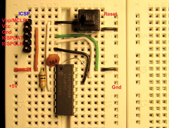
Besides, a 100 nF capacitors serves as the decoupling capacitor and should be placed close to the microcontroller. See the pictures below that show the whole arrangement made on the breadboard.

Figure 3: PIC16F688 with minimum support components on the breadboard.

Figure 4: Basic PIC16F688 circuit with a +5V power source plugged into the breadboard.

Figure 5 : Basic PIC16F688 setup circuit with a +5V power source and the programmer plugged into the breadboard.
Now you are pretty much set with the required hardware and software, and you are ready for your first experiment with PIC.
|
|
Dear RB,
1.the problem was loose connections, i attached the header pins to the icp01 programmer but it was not fitting properly
2.then i have taken some single strand wires and inserted in to the holes of the connector of the icp01 programmer and i used mplab ide software and this icp01 is recognized as pickit 2 and LED is flashing
3.i was using PIC16F677 microcontroller
4.but still the hex code generated from Micro C is not working but any how it was always fun reading your blog
5.i really should thank you for updating my knowledge on incircuit serial Programming.
1.after seeing your blog i purchased icp01 usb programmer.
2.i followed the installation procedure and installed pickit2 software
3.it is saying pickit2 connected ID=icp01- v2.0
4.when i load some hex file it says hex file loaded successfully
5.but when i program the device it says device not found etc…
Thanks & regards
Bhavani Sankar Appalla
Hey,
Awesome site! Really handy when learning how chips work.
How can I see what’s already programmed on a PIC16F688 micro-controller? :d
I have build the circuit and trying to get it to work. Right now, I am using off-Board Programming (Adapter) method. Would that be any different from the above procedure? The PICkit2 would load successfully every time, but it would not work on my board. Any Suggestions would be appreciated.
Tell me, could you tie Pin RC0 to MCLR and cause a reset from within code?
I have built the circuit, checked it and double checked it. I don’t have the regulated 5v turned on, but in the PICkit 2 programmer (I have the iCP01) it always just tells me ‘No Device Detected’. Any suggestions?
Check your circuit again, it should detect the PIC16F688 microcontroller. Try removing the reset switch from the circuit. If the switch is faulty, it could pull the MCLR pin to ground permanently.
Wow…. man greatest site I ever so about PIC micros….
keep up this great works please….
Hamza,
While programming the microcontroller, you don’t need an external power supply, all +5 V terminals will be driven from the ISCP programmer’s +5 V. But once the microcontroller is programmed, the application circuit should be powered from an external source as the programmer may not source the required current for the circuit.
is that ,we need to give separate +5v power supply for breadboard or v take from icsp +5v and given to the breadboard
I like what I see so far, a nice no pressure introduction to PIC micros and how they work.
Keep up the good work
Thanks, Kevin.