Lab 17: Sleep and Wake PIC microcontrollers
|
|
PIC microcontrollers’ Sleep feature is an extremely useful mechanism to minimize power consumption in battery-powered applications. In Sleep mode, the normal operation of a PIC microcontroller is suspended and the clock oscillator is switched off. The power consumption is lowest in this state. The device can be woken up by an external reset, a watch-dog timer reset, an interrupt on INT0 pin, or port-on-change interrupt. In this experiment, we will discuss how to put a PIC microcontroller into Sleep mode and compare the current consumption during Sleep mode and the normal operation mode.

Understanding Sleep mode
Theory
In Sleep (Power-down) mode, a PIC microcontroller is placed in it’s lowest current consumption state. The device goes into Sleep mode by executing a SLEEP instruction. The device oscillator is turned off, so no system clocks are occurring in the device. However, the I/O ports maintain the status they had before the SLEEP instruction was executed. Therefore, in order to minimize the power consumption in Sleep mode, the output ports must not be sourcing or sinking the current before going into Sleep mode. Besides, all the unused I/O pins should be configured as inputs and pulled either high (VDD) or low (VSS).
Several events can make the device wake up from the sleep mode:
1. Any device reset.
2. Watchdog Timer Wake-up (if WDT was enabled).
3. Any peripheral module which can set its interrupt flag while in sleep, such as:
- External INT pin
- Change on port pin
- Comparators
- A/D conversion
- Timer1
- LCD
- SSP
- Capture, etc.
The first event (device reset) will reset the device upon wake-up. However the latter two events will wake the device and then resume program execution. When the SLEEP instruction is being executed, the next instruction (PC + 1) is pre-fetched, so that on wake-up the processor could execute the next instruction after the SLEEP command. For the device to wake-up through an interrupt event, the corresponding interrupt enable bit must be set (enabled). Wake-up is regardless of the state of the GIE bit. If the GIE bit is clear (disabled), the device will just wake up from sleep and continues executing the program from the instruction right after the SLEEP command. If the GIE bit is set (enabled), the processor will execute the instruction after the SLEEP instruction and then branches to the interrupt address (0004h). Therefore, if an interrupt is to be used just to wake up the PIC microcontroller, the GIE bit must be cleared before the sleep instruction.
Watchdog Timer (WDT)
The Watchdog Timer or WDT is an independent timer with its own clock source. It provides a way for the PIC processor to recover from a software error that obstruct from program continuation, such as an endless loop. It is a free-running timer which, if allowed to overflow, will automatically reset the PIC. The WDT is enabled/disabled by a device configuration bit, WDTE. If it is enabled, software execution may not disable this function. To prevent a time-out condition the watchdog must be reset periodically via software. In PIC16F628A (the PICMicro used in this experiment), the watchdog timer has a nominal time-out period of 18 ms, which can be extended up to 2.3 s by using a prescaler with a division ratio of up to 1:128. The prescaler rate is selected through PS0-PS2 bits of the OPTION register. Note that the PSA bit must also be set to assign the prescaler to WDT, otherwise it will be used by Timer0.

Set PSA bit of OPTION register to assign prescaler to WDT
In normal operation, if the watchdog timer is enabled, a WDT reset instruction (CLRWDT) is placed in the main loop of the program, where it would normally be expected to be executed often enough to prevent the WDT overflow. If the program hangs, and the CLRWDT instruction is not executed in time, the program counter is reset to 0000 so that the program restarts.
However, if the PIC microcontroller is in Sleep mode, a WDT time-out will not reset the device, but just causes it to wake up (known as WDT wake-up) and the microcontroller continues program execution from the instruction following the Sleep instruction.
Note: When a Sleep instruction is executed, the watchdog timer is cleared. But the WDT will keep running if it has been enabled.
Sleep mode is extremely useful in battery-powered data-loggers where the measurement samples are to be taken with some sampling interval. Between successive data samples, the microcontroller can be put into Sleep mode to prolong the battery life.
Experimental Setup
The setup for this experiment would be as shown in the circuit diagram below. The PIC16F628A microcontroller runs at 4.0 MHz clock using an external crystal. An LED is connected to RB0 port pin, which glows for .5 sec after every 4.3 second delay. During the first half of the delay (2.3 sec), the microcontroller is put to Sleep mode and a WDT time-out wakes it up. The remaining 2 sec delay is created through a software routine using NOP instruction. An ammeter is connected in series between the power supply voltage and the microconroller circuit to monitor the current consumption of the circuit. The MCLR pin is pulled high through a 10 K resistor.

Circuit diagram for Sleep mode experiment

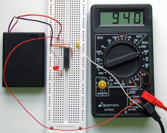
PIC setup on breadboard

Complete experimental setup
Software
The following program is written in C and compiled with mikroC Pro for PIC. The OPTION register is configured to assign prescaler to WDT. The prescaler ratio of 1:128 creates the WDT time-out duration of approximately 2.3 sec. An additional software delay of 2 sec is created using the Delay_ms() library routine. The amount of current consumption during both the delay intervals is displayed on the digital ammeter.
/* Project name: Understanding sleep mode in PIC microcontrollers * Copyright: (c) Rajendra Bhatt * Test configuration: MCU: PIC16F628A Oscillator: XT, 4.0000 MHz */ sbit LED at RB0_bit; // LED is connected to PORTB.0 void main() { TRISB = 0b00000000; TRISA = 0b00100000; LED = 0; OPTION_REG = 0b00001111; // Assign 1:128 prescaler to WDT do { asm sleep; // Sleep mode, WDT is cleared, // and time out occurs at Approx. 2.3 Sec // Current is minimum in Sleep mode LED = 1; // After wake-up the LED is turned on Delay_ms(500); LED = 0; asm CLRWDT; // Clear WDT Delay_ms(2000); // Measure current here and compare with Sleep mode }while(1); // current } |
The watchdog timer should be enabled in the configuration registers. In mikroC, this can be done through the Edit Project window (see below).

Enabling WDT from Project Edit window in mikroC Pro for PIC
Output
The current consumption during software delay routine (LED is off) was found as high as 940 µA, whereas the Sleep mode current was only 43 µA. This is a significant reduction in PIC’s power consumption.

Normal operation current

Sleep mode current
Summary
PIC microcontroller’s Sleep mode is a low current mode where the power consumption is minimum. It is extremely useful in battery-powered applications to prolong the battery life. If you are making a battery-powered data logger, it would be a smart move to put the microcontroller into Sleep mode during the time when it is not sampling the data value, and it can be waken-up by WDT time-out. In PIC16F628A microcontroller, the use of Sleep mode with WDT wake-up provides a maximum sleep duration of 2.3 sec. But if your data logger design requires a longer sampling interval between two successive data samples and you want to put the microcontroller into Sleep mode during most of this interval, you can use multiple SLEEP instructions in sequence. When the microcontroller wakes up from the first sleep by WDT time-out, it resumes normal operation and executes the next instruction. If it finds another SLEEP instruction, it will reset the WDT and go back to Sleep mode again, thus prolonging the sleep duration. The test circuit used in this experiment illustrated that the PIC current consumption is significantly lower (more than 20 times less) in Sleep mode than in normal execution mode.
|
|
Hi! Nice tutorial!
I’m implemeting sleep mode using pic18f27j13. The lower current is 2mA, in sleep state. The code is similar with your code. Can you help me? I don’t understand what’s missing for this to work.
Could you help me make the code for sleep mode for a c18 compliant, and PIC 18F458
I built same circuit and wrote same program in MikroC with 16F628A,, but my Ammeter shows : 6.63mA (led off) and 12mA(led On)
why it can be happen so high Amper ?
Thanks
Onur
Hi! I’m working with p18f45k20 and I’m making consumption measurements between sleep mode and run mode. I have 2 routines, one with sleep instruction that wake up with INT0 interrupt and other without sleep instruction that works in run mode. My surprise is that when I make measurements with first and the second routine, the power consumption is the same!!
I debugged the sleep routine and it is in sleep mode!
Something suggestions?
Best regards.
Nice article.
As I understand an enabled external interrupt during sleep will cause the micro to exit sleep.
1) Does the micro automatically reset the Watch Dog Counter when this happens?
2) Can the Watch Dog Counter and the value of the Postscaler be read?
I ask the above, as such automatic clearing of the WD Count would make it impractical to use the WD Counter to sleep the micro for a specific time, if some external hardware interrupt would result in the WD Counter being cleared either by the micro on exiting sleep or when a subsequent sleep is executed, without being able to read the WD Counter and/or WD Postscaler.
Nice article.
As I understand, an interrupt (eg a pin change interrupt) during sleep will cause the micro to exit sleep mode and execute the instruction after the last sleep instruction. If the int was enable the micro will then branch to the ISR.
Question:
1) Is the WD Timer Count (WDT) or the pre/post scaler automatically reset by the micro (eg 16F1823) when an enabled interrupt occurs during sleep?
I ask this as it would cause timing errors if you used the WDT to make the micro sleep for a specific time and you had some asynchronous interrupts occurring.
2) Can the WD TImer Count be read?
JJ
Hey, I really like this post.
Can you please put Deep sleep in pic24fj128ga310. I just want to see the basic deep sleep coding.
i am unable to do it.
Just an FYI – if you’re trying to maximize your power savings disabling Brown Out Detect will help reduce your power demands while sleeping. In my test this morning with a PIC12F683 sleeping with BOREN ON drew about 87μA while setting BOREN OFF reduced current consumption while sleeping to 2μA. This was using 5V Vdd.
There is also BOREN = NSLEEP available (at least with the 12F683), which keeps the brown out reset available while the chip is awake, and automatically disables the BOR on sleep.
Hi Raj! Does it works too without the crystal or resonator?
thank you soo much!
marC:)
In the sleep mode that you demonstrated is it just the CPU that gets switched off. If yes, how can I switch off the peripherals too. Is deep power down available in 16f and 12f series, like the ones in AVR which allows the peripherals to be switched off too.
Thanks man it would be relaly helpful if my project is powere by any lithium battery power source 🙂
excellent, I served my apprenticeship
Thanks for a good article, the PIC-noob in me seems to understand what you say… 🙂
Best article… Thanks..
Pingback: Sleep and Wake PIC microcontrollers / Cooking Hacks Blog
typo? …all the unused I/O pins should be configured as inputs and pulled either high…
I think you meant to say configured as OUTPUT. That’s your code states…
Great article!
@ I. Ramos,
It wasn’t a typo actually. The unused I/O pins must be configured as inputs and pulled either high or low to further minimize the current in Sleep mode. However, the example in this article was rather focused on showing how to put a PIC in Sleep mode, and wake it up with a WDT run out. The unused pins are just ignored but in real applications you should define them as inputs and tie to either Vcc or Ground for better performance. Thank you for pointing this out, I should have mentioned it somewhere on the article.
Hi, I have implemented the timer module using interrupt.
Can I use my timer module to set sleep for 15mins and wake up if there ‘s any signal for data logger purpose?
I never experience this kind of function before.
Regards
Linspire
The oscillator is turned OFF during Sleep mode and therefore, the Timer0 module cannot be used for wake up. That’s why you should use WDT which has its own clock. You can also use Timer1 module operated as a oscillator. See the datasheet for more details.
R-B you are correct 🙂
Pingback: Electronics-Lab.com Blog » Blog Archive » Sleep and Wake PIC microcontrollers
Pingback: Stretch your circuit’s battery life by putting your PIC to sleep | You've been blogged!
Thank you very much.
I was actually implementing the WDT/SLEEP combination in some pic code yesterday.
But I do think that when a wakeup-on-pinchange occures, it is not PC+1 thats gets executed but it starts at the reset vector, just as with a normal powerup (but with a few special bits cleared. This is at least the case with PIC 12F508/9
Hey Benjamin,
I checked the datasheet for PIC12F508/9 and it clearly says that wakeup-on-pinchange and WDT time-out reset the PIC. But it is not always the same. PIC12F683 does continue the execution from PC+1 after waking up from Sleep either by WDT or interrupt-on-pin change, and so does PIC16F628A.
Pingback: Stretch your circuit’s battery life by putting your PIC to sleep | The Depot of Talk
Pingback: Întinde via?a circuit a bateriei prin punerea PIC dvs. pentru a dormi | ro-Stire
Nice page!
I always replace batteries when they display the warning, because it can affect the meter’s accuracy.
I even fried a laser once because when it read 40mA the diode was actually receiving nearly 50mA.
Kind regards, -A
Pingback: Stretch your circuit’s battery life by putting your PIC to sleep - Hack a Day
keep up the good work. i appreciate it
Nice tutorial!
thank you and we hope moer