Stereo audio amplifier using TEA2025 chip
|
|
While LM386 is the most popular audio amplifier IC among hobbyists, it provides the limited output power of only 1 Watt, and for stereo application, two LM386 ICs are required. This project is about making a 5 Watt stereo audio amplifier using the UTC TEA2025 IC chip.

Stereo audio amplifier circuit enclosed inside a plastic box
Theory
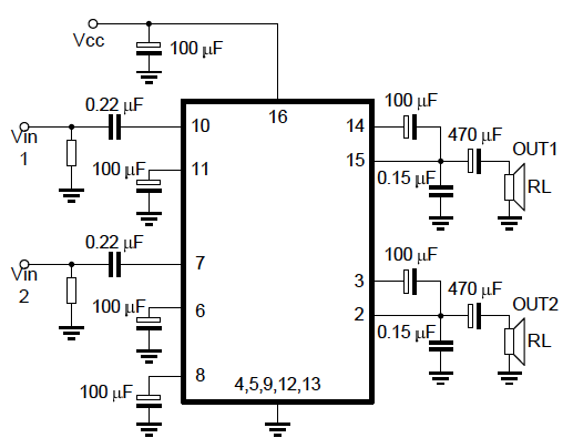
The UTC TEA2025 is a monolithic integrated audio amplifier IC in a 16-pin plastic dual in line package. It is originally designed for portable cassette players and radios, but it can be used to make a pretty decent stereo audio amplifier for an ipod or mp3 player. It requires very few external components and can run on as low as 3 V power supply. The pin diagram of TEA2025 and the application circuit for stereo application are shown below.

Pin diagrams of TEA2025 (from UTC TEA2025 datasheet)

Stereo application circuit for TEA2025 (from UTC TEA2025 datasheet)
The device provides the maximum gain of 45 dB. However, it can be lowered by placing an external RC series circuit between the feedback pin (6 and 11, see pin diagram) and ground. The datasheet recommends not to reduce the gain under 36 dB. In order to get the maximum gain, use R=0 and C=100 µF (as shown in the application circuit above) between the feedback and ground.
The low cut-off frequency (fL) of the output signal depends upon the load resistance (speaker, RL) and the output capacitor 470 µF. If the speaker resistance is 4?, the low cut-off frequency will be,
fL = 1/(2? CRL) = 80 Hz
An interesting characteristic of TEA2025 is it has built-in thermal protection circuit. If you want to run it at its full capacity (5 W), you should provide a heat sink in the circuit. In case you don’t, the internal thermal protection won’t let the device damage; all that happens is that the output power is reduced when an excessive junction temperature is sensed.
At the input stage, a logarithmic dual taper potentiometer (10 or 20 K) can be used to provide the volume control feature. The 0.22 µF capacitors at the input side help to minimize any noise due to variable resistor contact. The 0.15 µF capacitors at the output end are for frequency stability. Use of other value capacitors could result in unwanted oscillations at the output. Long wire connections and ground loops in the circuit could also cause oscillations, so a good layout of the circuit PCB is very important.
I built this circuit on a 5 cm x 9 cm general purpose prototyping circuit board as shown below. The circuit is put inside a 6 cm x 11 cm size plastic enclosure and necessary connections (power supply, speaker, and stereo input terminals) are drawn out of the box. The circuit can be powered from 3-12 V power supply. I am powering this with my spare 9.6 V rechargeable battery from my broken RC toy. I am happy with the performance of TEA2025 as an stereo audio amplifier.

TEA2025 circuit board

Circuit is powered by a 9.6 V rechargeable battery (NIKKO) from a RC toy

Completed project
Project in action

Connecting a logarithmic dual taper potentiometer at input sides
|
|
This chip runs too hot so how to add heatsink ?
Also, there is too much clipping when volume is raised. How to fix it ?
I only saw 1 potentiometer instead of two as shown in the circuit. Is there any reason for that?
It’s a dual potentiometer. In simple terms, it means 2 pot-in-1 package.
In the finished circuit I can only see 1 potentiometer instead of two as shown in the circuit. I’d there any reason for that?
Can you provide PCB layout for me??
I built it and it cool, nice bass. Kudos
I built that amp. And it cool,
nice bass. Kudos
Hi, this chip is fine, as long as power supply stays at or below 12V nominally (15V peak). At this Vcc a heatsink is recommended, tho. Some additional notes:
Best to lay 100nF close to chip pins between Vcc and ground, additional to 100 uF as shown. This raises stability.
Best to lay 100 pF between input and feedback, lowering susceptibility for radio. (softer chirps from mobiles)
Best to use a bigger input cap, say 2.2 uF, because low source resistance raises power supply noise suppression. (less hum)
Best add 150 Ohms in the feedback path, for you know 100 uF in series with 150 Ohms to ground. This lowers gain (but gain will be still hi enuf for walkmans and smartphones) and clang (harmonic distortion).
Best lay 2.2 Ohms in series with the 150 (or 100) nF cap at output. This raises stability.
Uli
this amplifier circuit works very very super o k with great bass output and a very good concert stereo widening I really enjoyed it through out the whole last night .
but this morning I was about powering it then I miss placed the polarity ,guess what ?___I fried my new amplifier, am about crying now.
you can always put diode for protecting your circuts
I like electronics
what can i replace the 0.15 caps with.
i cant find them in my local store. really need ya help.
I still cant get away wit de noise 4rm de amp nd no sound was comin out wen i connect 2 speaker till i connect V to de amp output pin
you will not mention the diodes and siramic cepecitance is how to connect in circuit
I made the whole circuit but its doing the opposite ,the output very low
I made this circuit yesterday. As soon as i power it up, it starts making wind like noise. The only change i made to the circuit is i changed the 0.15 and 0.22 caps to 0.1 uf. Please help!!
I have tried this and the speaker at pins 3 and 2 works fine. . But when connecting the other one on pins 14 and 15 ,I get a low sound and a lot of noise . .
Why is that happening?
And the pin 12, does that have to be grounded through 100uf cap?
Try with a reliable power source with good amp capability and filters.
In your pic , I saw a diode , what is the value for that ? and the white thing beside the IC , what’s that ?
Very nice description
Hi, is it really so bad with bass? Or the video is bad quality?
Pingback: Amplificador de audio estereo con TEA2025 | Automatismos Mar del Plata
thanks rb great work i would say…. i m gonna try it today but as kyle said should i use tea 2025 or tea 2305.. looking forward for your response
Pingback: Pequeno Amplificador de Audio para PIC « Antonio Polo
I like the 16F1827 board but are there lessons on using that chip with the board?
Thanks, R-B; I’ll get to work. -S
I’ve never built an IC amp before and this one looks like a good one. Questions: I do not see the volume control in the schematic. The two symbols from input to ground I don’t recognize, is that where the pots go? The picture shows what looks like a fixed value resistor on the board and I don’t see it in the schematic. Your elaboration would be appreciated. -S.
Steven,
I added a drawing at the end of the post that shows how to connect a potentiometer at the input side.
Pingback: Electronics-Lab.com Blog » Blog Archive » TEA2025: An stereo Audio Amplifier IC
Quick note. Just after the fL formula, you mislabeled the chip as a TEA2305 rather than a TEA2025. I would have mentioned this in private, but, I didn’t see a quick way to do so.
Kyle,
Thanks for pointing that out.
very very nice small circuit design . i m gonna make it . 🙂
Pingback: Amplificador de audio estereo con TEA2025 : Audio Room