Wireless data transmission between two PIC microcontrollers using low-cost RF modules

|
|
A lot of times we need to keep track of data from a device or a sensor located in a remote location from the point where it is processed. In other situations we desire wireless solutions for ease. Using long cables, infrared (IR) or other means are often tedious and not loss-less. Imagine collecting pH level data from a chemically lethal or toxic treatment plant where human presence is highly health hazardous. Running long cables from the pH sensor to the control or monitor station will surely introduce noisy signals and signal-to-noise ratio will thus drastically decrease. The result is erroneous data acquisition and thereby false decisions may be generated. If infrared signals or other optical means including lasers are used, they will need good obstacle-free line of sight or expensive and delicate optical fibers. Thus the solution stays in the radio frequency (RF) domain. This article talks about interfacing low cost RF modules (KST-TX01 and KST-RX806) for transmitting data between two remotely located PIC microcontrollers.
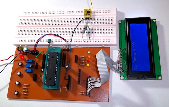
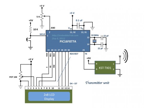
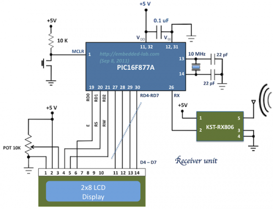
In this demo, we will see how to achieve an easy data transaction between two PIC16F877A microcontrollers using inexpensive RF modules. The theory is pretty simple and straight. It uses KST-TX01 and KST-RX806 RF modules which is a 433 MHz serial data transmitter/receiver pair. One PIC16F877A is programmed to transmit its ADC data (RA0/AN0 channel) serially using its built-in USART hardware at 1200 baud with no parity and 8-bit data stream. The PIC’s USART transmitter (TX) pin feeds the data into the data pin of the KST-TX01 which transmits it using 433 MHz ASK RF signal. On the receiving end the KST-RX806 module receives the data and its output is connected to the another PIC’s USART input pin. The second PIC is programmed to read its USART receiver (RX) pin. On both ends, two LCD displays are also connected which show the transmitted and received bytes. Since RS232 communications typically allow 8-bit data, the 8-bit A/D conversion is used here for simplicity, instead of the more common 10-bit ADC.
Software
The demo codes given for the receiver and the transmitter PICs are written using CCS PCWHD compiler. The firmwares are easy to understand and needs no explanation. In CCS PCWHD, the LCD pins are defined in the lcd.c file. By default, it uses the PORTD pins (as shown in the circuit diagram above) as connections to the LCD. If you are using a different port, you need to edit the lcd.c file accordingly.
Receiving side code
#include <16F877A.h>
#device *= 16
#fuses HS, NOWDT, NOPROTECT, NOLVP, PUT
#fuses NOBROWNOUT, CPD, NODEBUG, NOWRT
#use delay(clock=10MHz)
#use rs232(baud=1200, rcv=PIN_C7, bits=8, parity=N)

#include <lcd.c>

void main()
{
 byte c;
 lcd_init();
 lcd_putc("\f");
 while(true)
 {
 c=getc();
 printf(lcd_putc,"\fRx Data = %u",c);
 delay_ms(100);
 }
}
Transmitting side code
#include <16F877A.h>
#device *= 16
#device adc=8
#fuses HS, NOWDT, NOPROTECT, NOLVP, PUT
#fuses NOBROWNOUT, CPD, NODEBUG, NOWRT
#use delay(clock=10MHz)
#use rs232(baud=1200, xmit=PIN_C6, bits=8, parity=N)

#include <lcd.c>

void main()
{
 byte s=0;
 lcd_init();
 lcd_putc("\f");
 setup_adc_ports(adc_clock_internal);
 setup_adc(AN0);
 set_adc_channel(0);
 while(true)
 {
 read_adc(adc_start_only);
 while(!adc_done());
 s = read_adc(adc_read_only);
 lcd_gotoxy(1,1);
 printf(lcd_putc, "\fTx Data = %u" s);
 putc(s);
 delay_ms(100);
 }
}
Summary
Thus we saw that KST-TX01 and KST-RX806 RF modules are very easy to use for RF transmission and reception of data as they can be directly interfaced to the UART port of microcontrollers. However, there are few things that I noted while experimenting with them. One is, when the ADC value (8-bit in this demo) is around 250 or higher the receiver starts getting garbage data. It seems like when the data contains too many 1s, it is not recognized by the receiver which literally “believes” that the data is static. One solution could be dividing the ADC byte into two nibbles and send them separately. It will slow down the net data transmission rate but the received data will be less likely to be erroneous. It also adds an extra overhead of reconstructing the bytes from the nibbles. Similarly, if you want to use 10-bit (or more) resolution for A/D conversion, the ADC result can also be broken into two 5-bit fragments (MSB 5-bit and LSB 5-bit) before transmission. Adding three extra 0s on the MSB end of each fragment completes the transmission byte. By doing so, the numerical value of each data byte will be less than 32.
Another important fact to note is the range of the modules. Many manufactures claim ranges of up to 10m or so. In reality this may not be what they claim because of the antenna length and the quality of the modules themselves. A wire of 12 inches or so is adequate for a reasonably good wireless communication.
Lastly, I found the two RF modules perform best at 1200 baud. While data transmission at 2400 baud is also possible, it will not be error free. Baud rates more than that are not useful at all. Several improvements can be done to add more features but I have kept it for those who are willing to explore it more and use it in various purposes.
The lesson from this demo can be expanded to a wide range of applications. Here are some common applications:
- Remote appliance controllers,
- Wireless headsets,
- Remote data acquisition systems,
- Surveillance and security systems,
- Robotics,
- Hands free devices,
- Digital radios,
- X-bee and Bluetooth,
- Navigation systems,
- Toys and so on.
Many thanks to Shawon Shahryiar for contributing this article to Embedded Lab. He works as an Engineer in the Research and Development Cell at ELECTRO Group in Dhaka, Bangladesh. You can contact him at: |
 |
|
|


Great post! Have nice day ! 🙂 lfiqw
Can I get a codes for encryption of message at transmitter side and decryption at receiver side. To make secure communication but the circuit remain . Please help me
im new to programming and i have only recently started experimenting with microC, i wanted to plagiarize this for my school project but the code doesn’t build on microC compiler, what compiler works with this code?
why 10MHZ OSCILLATOR,. 1UF CAPACITOR ARE USED?
what is the cost of this project???
how to interface bluetooth module HC-05 with micro controller .plz give me the program in c or assembly language
I am facing a problem in communication between the RF modules with the microcontroller (8051 chip) that doesn’t include UART port, so how can I connect these 2 modules with the 8051?
Create software UART or use special protocols like Manchester code….
how can work the pic16f877a micro controller in rf based wireless encryption and decryption message transfer system in military system.
can i use these RF tx and rx and the given code for room automation system?
halp me please i need this project Transmission de données sans fil entre deux microcontrôleurs de PIC
HOW CAN USE CAPTEUR OF TEMPTARTURE IN THIS PROJECT
how to transfer data between two pic microcontroller using bluetooth modules ?
Can you give me assembly source codes for the above (RF Communication) project ?
using the above code can i type the required data outside the pgm that means can i send data alternately or i want send data which is frequently changing. so i want to type data and give send, i need a keyboard interface for this please help………..
Hi,
I am trying to do something similar using a thermocouple, 2 arduinos and 2 Xbee RF modules. Any hint?
hello
I’m working on a similar project but unlike the transmitter with a 16f877a. I’m doing them a 18F4550 and I can not make it work for k maybe missing lines of code I need help please.
HI Raj!
i would like to do a wireless door bell, can you help?
thank you!
marC:)
hello. this is useful project. i wanna measure distance between 2 RF module (between TX and RX), please tell me how to measure distance? i wanna make like this device
http://www.amazon.com/Safety-Wristband-Anti-Lost-Protect-outdoor/dp/B007SBR0AM
Do I need to configure KST-TX01 and KST-RX806 by sending some specific code before using it or I can use it directly.I am asking it because I am working with ATMEGA-16 and I didn’t understand some(FUSE) part of your programming.
@ moderator, how can i directly access mr Shawon..there’s been no response from that mail add.
thanks
@ Antonio, i did run it in proteus and it worked, though after compiling and debuggin on ccs c.
hello there . well im a student working on a project with RF and i need to simulate this on proteus . if you can tell me how to simulate this ( cant find the module of KST- tx01 and RX module ) i would appreciate the help
hello .how did you run it on proteus ( have isis 8 and i cant find kst-rx / tx composant) or did you created them ? a little help whould be great i m stuck
Hello.Thanks a lot for your very great project,Would you please
design a project so that two PICs can communicate with RS485 and
even send for example a few numbers of 10 digits to each others
and on the LCD?
Thanks,
Can this be tested in Proteus? Did you do it?
v want to interface 4-wire resistive touch screen with pic16f887 & how i can do it.i need coding for that.i also need a coding to transmit the data through zigbee
Hello , this transmitter and reciever works with ASK modulation ,
does the transmitter that works with modulation AM , can be used the same way ?
hi RB
thanks for your posts
i am working in an electricity active energy metering system, but i did not find how to make the same meter based PIC take the energy consumed into account even if the phase and the neutral are inverted for a single phase case.
Hi Engineer
im doing a similar project although the difference is that i want the two picocontrollers (PIC16F877A) to be able to send and receive data from the other.can you help with mikro C code for the realisation of the transmission.
I have tried to make communication between two uc by KST TX01 & KST RX806 according to your connection but with atmega8.I did not find any output.Instead of KST TX01 & KST RX806 when i connect two uc by a wire then my program works but when i place KST TX01 & KST RX806 i did not find any output.where could be the problem. my code in mikroC is following
TX:
char uart_rd;
void main()
{
UART1_Init(960); // Initialize UART module at 9600 bps
Delay_ms(1000); // Wait for UART module to stabilize
while (1)
{
UART1_Write_Text(“a”);
Delay_ms(1000);
}
}
AND RX:
char uart_rd;
void main()
{
DDRB=0xFF;
PORTB=0x00;
UART1_Init(960); // Initialize UART module at 9600 bps
Delay_ms(1000); // Wait for UART module to stabilize
while (1) { // Endless loop
if (UART1_Data_Ready()) { // If data is received,
uart_rd = UART1_Read(); // read the received data,
if(uart_rd==’a’)
{
PORTB0_bit=~PORTB0_bit;
}
}
else
PORTB4_bit=~PORTB4_bit;
}
}
bro im doing same project.
add me on skype:
navid.bin.ahmed
sorry your baud rate wrong not 960.
.
its 9600.
Pingback: problem with Servo and Stepper motor
the source code given above gives me error can u plz mail me the source code which is error free…..amna-1991@live.com
Amna91,
I would suggest you to contact Shawon regarding this. His email address is provided at the end of the article.
can u tell me what other transeciver i can use because the pair u r using is not available in the market….. plz reply soon. amna-1991@live.com
Do you have the hex files for this programs so I can program my pics on Mplab?
Sorry, I don’t. But you can compile the source program provided.
Pingback: Wireless data transmission between two PIC microcontrollers using low-cost RF modules | Look4tech.com
If streams of constant data is a problem why not try manchester encoding? Each bit (x) is is transmitted twice in effect as x^0 and x^1. Also it’s self clocking
thanks RB for your posts about microcontrollers,if you are able to give me a little help and advice about active power metering using mikroC and PIC18F452;
hamid,
I am extremely busy right now to help on this. But you can search online for resources:
http://www.microchip.com/stellent/idcplg?IdcService=SS_GET_PAGE&nodeId=2138¶m=en025183
http://atmel.com/dyn/resources/prod_documents/doc2566.pdf
http://ww1.microchip.com/downloads/en/AppNotes/01291b.pdf
You can implement the concept with whatever microcontroller you want.
thank you RB for your help
Pingback: Electronics-Lab.com Blog » Blog Archive » Wireless data transmission between two microcontrollers using KST-TX01 and KST-RX806 rf modules
where is lcd.c file ?
sahu,
Read this for more info on lcd.c file
http://seng.ulster.ac.uk/eme/sidk/resources/Eejits%20guide%20to%20using%20a%20LCD%20alphanumeric%20display.pdf