Multi-purpose dual power supply (5.0V and 3.3V) regulator board
|
|
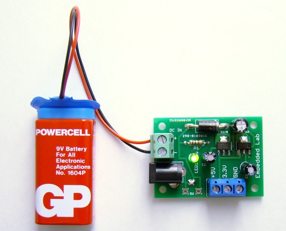
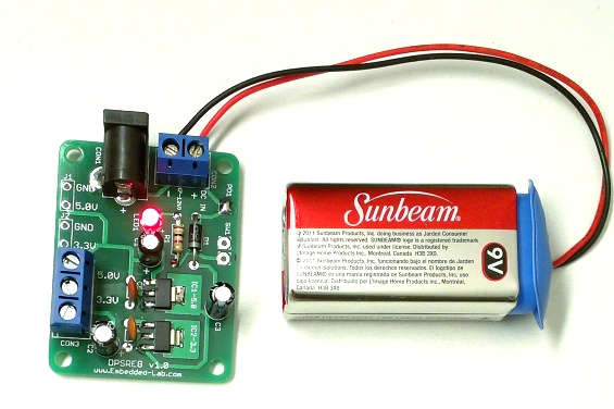
All embedded systems require electric power to operate. Most of the electronic components inside them, including the processors, can operate at a wide range of supply voltage. For example, the operating voltage range for the PIC16F1847 microcontroller is 2 to 5.5 V. But there are certain applications where you need a regulated constant voltage to avoid malfunctioning of the circuit or getting erroneous results. For instance, any application that involves analog-to-digital conversion (ADC) requires a fixed reference voltage to provide accurate digital count for input analog signal. If the reference voltage is not stable, the ADC output is meaningless. Here is my latest dual power supply regulator board that provides constant 3.3V and 5.0V outputs from an unregulated DC input (6.5-10V). It is small in size and can be easily enclosed inside the project box along with a project circuit board. It can also be used to power test circuits on breadboard. The board uses two AMS1117 series fixed voltage regulators and receives input power through a DC wall wart or an external 9V battery.
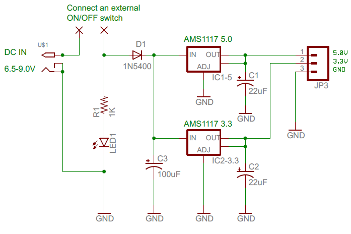
The regulator circuit uses two AMS1117 series fixed voltage regulators, AMS117 5.0 and AMS1117 3.3, to derive constant 5.0V and 3.3V outputs from an unregulated DC input voltage. The circuit diagram of the board is shown below.
Note that both AMS1117-3.3 and AMS1117-5.0 derive input power directly from the unregulated supply voltage, which means each of them can deliver up to 0.8A of current. However, for this particular board it is recommended to limit the output current up to 500 mA maximum. For the safety of the AMS1117-3.3 regulator IC, the unregulated input voltage is also recommended to be within 6.5 to 10.0 V. This board is best to use in a project that is designed tobe powered with a 9V DC from either a PP3 battery or a wall adapter. The PCB is only 1.9″ x 1.4″, and occupies a small area inside the project box.
The board doesn’t have any ON/OFF switch, because it may not be useful if this board is enclosed inside the project box. But through-hole pads are provided on the board if you want to add one externally. There are two surface mount pads which are shorted together by default with solder to close the circuit permanently. These must be disconnected if an external ON/OFF switch has to be added.
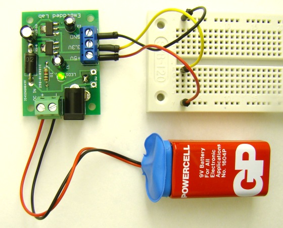
The regulated output voltages (5V and 3.3V) are accessed through screw terminal blocks. This power supply board can also be used to power breadboard circuits (see the picture below).
I have made few PCBs of this using iTeadStudio’s PCB service. If anybody need one, contact admin(at)embedded-lab(dot)com. It will be $5.50 for one PCB, $10.25 for kit (one PCB along with the components shown in the circuit diagram), and $11.99 for assembled board. Shipping (regular USPS) within the United States is included in the price.
Update (02/26/2013)
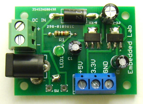
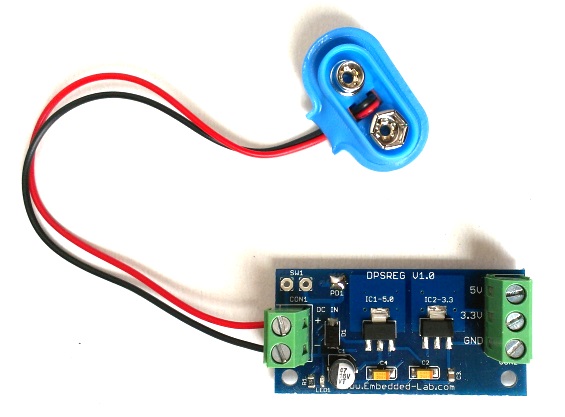
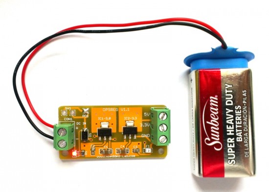
This board has been revised a little bit. The new board can have maximum DC input of +15V, but I would recommend to use below +12V to prevent overheating of the regulators. In the new board, the input to AMS1117-3.3 is derived from the output of AMS1117-5.0, so maximum recommended output current is 600 mA combined (5.0V and 3.3V). The price of the new assembled board is $10.50 plus shipping and can be purchased on Tindie. You will get a free 9V battery connector with the board. Following are the pictures of the new board.
Update (08/12/2013)
A new version of this board is released with a further reduction in the PCB size.
Update (02/22/2014)
A new revision is released with an onboard 500mA PTC fuse.
Tindie buying link: Dual Power Supply Board for only $6.99
|
|



I have an incubator that has a fan like in a computer there is a circuit board (small) that changes the 120 volt dc to 12 volt a.c. .02a can 1 buy one that does this as my board is fried ty
Hello
in the sixth picture you put two capacitors near AMS1117 3.3 and 5.0 , what value they have?
Thx
Or resistors…
They are 1 uF, ceramic capacitors.
Thx man … but can u tell pls in 2 or 3 words why you put them….
I’m a beginner
Where can i get the latest circuit diagram?
Tnks!!
Where can I buy this? A kit with all the components would be perfect but I’d even settle for just the pcb. Thanks!
Pingback: Fuente doble multiproposito (5V y 3,3V) | Automatismos Mar del Plata
I have an early version of the board. What format or part number would you recommend for a switch?
All my switches have three legs…. and I only have two holes in the PCB and neither of these are the common. 🙂
Can you help please?
Hi Evan,
The switch must be external and not on board. The two wires of the switch should connect to the board through SW1 pads.
hello, great job!, is it possible to have the update circuit diagram?
thanx a lot for this Circuit>
Pingback: Blog J.Schweiss | AVR Tutorials
Dave,
Email me at admin @ embedded-lab . com
Thanks!
How can I order the 5/3.3v?
How can I order the 5/3.3v p/s?
Where/how can I order some of the dual 5/3.3v power supplies?
Pingback: La semana en links (19/06/2012) | Automatismos Mar del Plata
Pingback: Dual power supply (5.0V and 3.3V) regulator board » ????? ??? ??? | ????? ??? ???