Assembly instructions for Easy Pulse kit

|
|
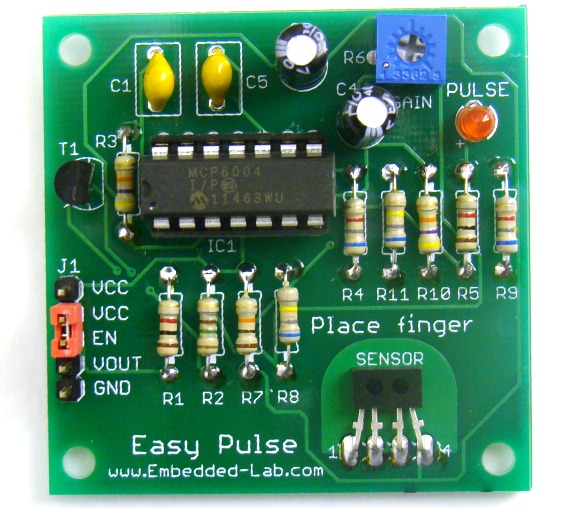
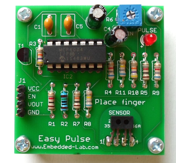
Assembling Easy Pulse kit is pretty simple and straightforward. There are two versions of PCBs which are mostly the same. In the second version the J1 connector has 5 pins instead of 4. I have added an additional VCC pin next to the EN pin. This would allow users to test the board quickly after being assembled. You can activate the sensor by simply placing a jumper between the EN and VCC pins, and the board is ready for operation. While soldering the parts, start with low profile components such as resistors and capacitors. This makes overall soldering process easier.
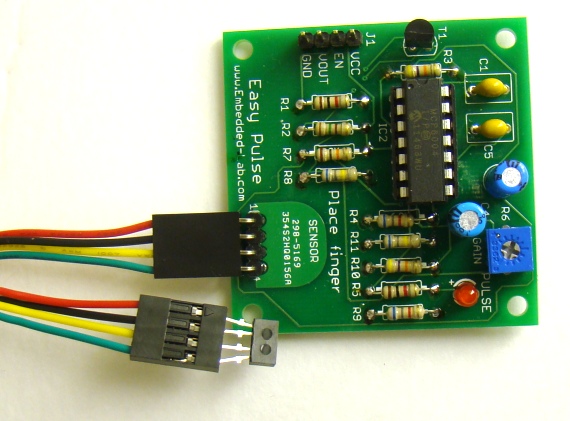
If you are using the jumper cable to connect the sensor to the board, make sure you connect the TCRT1000 pins correctly. Use the following picture as a reference while doing so.
After finishing assembling the board, you can test the board by placing a fingertip gently over the sensor, and keep the finger still. Make sure that the potentiometer is set to somewhere around the middle position. If you don’t see LED pulsing, you can increase the gain by further moving the potentiometer position in clockwise direction. You have to wait for a few seconds until the circuit gets stabilized.
|
|


Raj! I just bought the kit, can you help me interfacing with this project please?? : http://embedded-lab.com/blog/?p=1671
thank you!
marC:)