Introducing a new serial (SPI) 8-digit seven segment LED display module using MAX7219
|
|
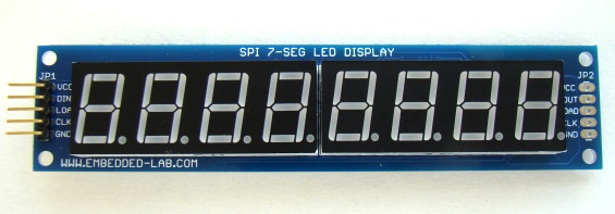
Seven segment LED displays are brighter, more attractive and provide a far viewing distance as well as a wider viewing angle as compared to LCD displays. The major drawback of using seven segment LEDs is they are resource-hungry. Time-division multiplexing is the most common technique of interfacing 7-segment LEDs to microcontrollers. With this technique, an 8-digit seven segment LED display with the decimal point requires at list 16 I/O pins of the microcontroller, which is quite a lot. Consequently, their use with low pin-count microcontrollers (such as PIC12F series) is not practically feasible. Here’s our latest version of the MAX7219 based serial seven segment LED display module (SPI7SEGDISP8.56) that will allow you to add 8 digits of seven segment LED displays to your project using only 3 I/O pins, and provides full control of all the digit segments including decimal points. You can even cascade two or more of these modules together without sacrificing any extra I/O pin. SPI7SEGDISP8.56 display kit is also available for purchase on Tindie for $12.99.
Circuit diagram
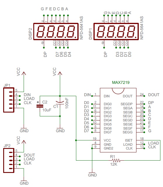
The SPI7SEGDISP8.56 display module is based on MAXIM’s MAX7219 display driver chip that provides a 3-wire serial (SPI) interface to drive 7-segment LED displays (common-cathode type) up to 8 digits. Included on-chip are a BCD decoder, multiplex scan circuitry, segment and digit drivers, and an 8×8 static RAM to store the digit values. The segment current for all LEDs is set through an external resistor. However, the device is also capable of providing a software control of the display brightness (16 steps from minimum to maximum) through an internal pulse-width modulator. For more details on the internal block diagram and operation of MAX7219, read my earlier project Serial 4-digit LED display and the product datasheet.
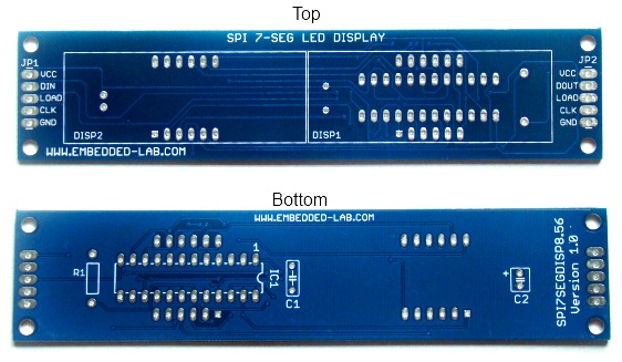
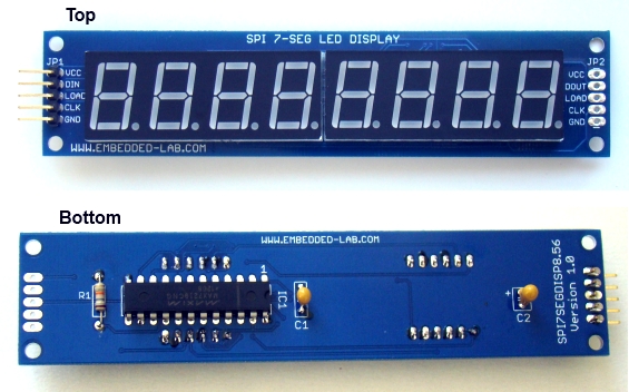
The circuit diagram of the SPI7SEGDISP8.56 display is pretty straightforward and follows the guidelines described in the datasheet. Two 4-digit CC LED displays (0.56″) are used in SPI7SEGDISP8.56 to form a joint 8-digit display. JP1 header provides access to power supply, DIN, LOAD, and CLK signal lines. Similarly JP2 contains the same signal lines except DIN is replaced by DOUT pin. This allows easy cascading of multiple displays. For cascading, DOUT from one MAX7219 goes into DIN of another. C1 and C2 are decoupling capacitors and R1 set the maximum current value per segment. Read the MAX7219 datasheet for more details on selecting the value of R1.
Interfacing examples
The SPI7SEGDISP8.56 module can be interfaced with any microcontroller that has 3 I/O pins available. If the microcontroller features a built-in hardware SPI, then the display module can be interfaced as a SPI slave device. In that case the SPI signal lines SDO (serial data out), SCLK (serial clock), and SS (slave select) from the microcontroller can be directly connected to the DIN, CLK, and LOAD pins of MAX7219. The LOAD signal is active low.
In case the host microcontroller doesn’t have a hardware SPI module, the interface can be implemented in software. In my previous project (Serial 4-digit LED display) I have described how to write a software SPI routine to drive the MAX7219 based LED display module using three general purpose I/O pins of the PIC12F683 microcontroller. Same guidelines can be followed to write display routines for the SPI7SEGDISP8.56 module.
SPI7SEGDISP8.56 and Arduino
The LedControl library allows you to easily interface MAX7219-driven seven segment LED displays to Arduino. The library also supports cascading of multiple MAX7219 devices (maximum 8 devices). The following Arduino sketch is an example of interfacing one SPI7SEGDISP8.56 module. It displays numbers 1 through 8 on the eight 7-segment LED displays of SPI7SEGDISP8.56.
#include "LedControl.h" // Arduino Pin 7 to DIN, 6 to Clk, 5 to LOAD, no.of devices is 1 LedControl lc=LedControl(7,6,5,1); void setup() { // Initialize the MAX7219 device lc.shutdown(0,false); // Enable display lc.setIntensity(0,10); // Set brightness level (0 is min, 15 is max) lc.clearDisplay(0); // Clear display register } void loop() { for(int i=0; i<8; i++){ lc.setDigit(0,i,i+1,false); } delay(1000); } |
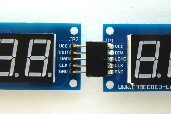
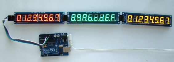
For cascading a second MAX7219 device, the DOUT pin of first device should be connected to DIN pin of other, and corresponding CLK and LOAD pins must be tied together. In SPI7SEGDISP8.56, DOUT pin is accessible through JP2 header. JP2 and JP1 header pins are compatible for direct cascading (see the picture below) by plugging them together.
The following Arduino sketch illustrates daisy-chaining three SPI7SEGDISP8.56 modules using the LedControl library.
#include "LedControl.h" // Pin 7 to Data In, 6 to Clk, 5 to LOAD, number of devices is 3 LedControl lc=LedControl(7,6,5,3); void setup() { // Initialize the 3 MAX7219 devices for(int k=0; k<3; k++){ lc.shutdown(k,false); // Enable display lc.setIntensity(k,15); // Set brightness level (0 is min, 15 is max) lc.clearDisplay(k); // Clear display register } } void loop() { int count = 0; for(int j=0; j<3; j++){ for(int i=0; i<8; i++){ lc.setDigit(j,7-i,count, true); // Decimal point enabled count ++; if(count == 16) count=0; } delay(1000); } } |
SPI7SEGDISP8.56 display kit is available on Tindie for $12.00.
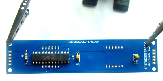
Soldering parts is pretty easy. The MAX7219 chip, resistor, and capacitors are soldered on the bottom side whereas the LED displays go to top side of PCB. The PCB size is approximately 4.8″ x 1.1″ (12.3cm x 2.8cm). Detail assembly instructions are available here.
Tindie buying links:
SPI7SEGDISP8.56 buying link – Red color
SPI7SEGDISP8.56 buying link – Yellow color
SPI7SEGDISP8.56 buying link – Green color
SPI7SEGDISP8.56 buying link – Blue color
Buyers from countries other than USA can also use following links for lower shipping cost
SPI7SEGDISP8.56 buying link – Red color
SPI7SEGDISP8.56 buying link – Yellow color
SPI7SEGDISP8.56 buying link – Blue color
|
|


Sketch will not compile for Uno. I get error message:
Arduino: 1.8.4 (Windows 10), Board: “Arduino/Genuino Uno”
C:\Users\mdoti\Documents\Arduino\MAX7219_demo\MAX7219_demo.ino: In function ‘void loop()’:
MAX7219_demo:15: error: ‘lt’ was not declared in this scope
for(int i=0; i<8; i++){
^
MAX7219_demo:15: error: expected ‘)’ before ‘;’ token
for(int i=0; i<8; i++){
^
MAX7219_demo:15: error: ‘i’ was not declared in this scope
for(int i=0; i<8; i++){
^
exit status 1
‘lt’ was not declared in this scope
I’m trying to build and install a 7-segment LED display consisting of 8 displays. These will be using in my car (2001 BMW 330Ci) to display oil temperature, oil pressure and water temperature. All sensors are resistive. The temperature sensors are NTC thermistors. I want to mount the displays in the strip of dash between the center vents and the top of the head unit. There’s about 3/4″ of vertical room; 7″ of horizontal space. I need to multiplex the displays because of the lack of space for wiring. I realize that all 3 sensor streams need be ADC’d. The 3 data streams will need to go through a mux. This is where I get lost. Can you please provide help?
Thanks,
Marco
Hi. I like your 8-digit seven segment display module; however, I would like yo use it with .28″ LED to match a display from a DDS signal generator. Would this be possible? Since this would be for a one of a kind project I could use a ribbon cable if necessary. Best for me would be 2x 16DIP sockets.
Thank you,
Hal
Hi, has anyone have a C library or example for a stm32f103c8 arm mcu?
Hi sir i working with led display Can I cascade more than 8 using Max7219 & how to initialize two 7219 .how to write code for cascade …
How tall are the digits?
Hi, i have a question can i control the individual digits of the array of 7 segments,. since the data is multiplexed am i transferring the whole sets of data for whole digits or can in be updated individually,.
Essentially, can i used it in RTC applications, and if it feasible displayed up to seconds,. thanks
Darren,
Yes, you can control individual digits separately.
thanks for the info,. i have obtained one module of it,. now im tinkering with it,. hoping to do some neat clock works like moving its digit arrays, do simple pattern and controlling it brightness,.
Can I cascade more than 8 Max7219 chips using ledcontrol.h? Is it a software or chip problem? I am needing 10, but not able to get the last 2 to work
How do you clear (turn off) a single digit?
Pingback: SPIでデイジーチェーンできる7セグがTindleで$12 – OnBoard PRESS Japan
My query of December 19 2015 was picked up by Raj, who immediately contacted me and suggested that I should change “WProgram.h” into “Arduino.h” within the LedControl.h file. I did this but it still wouldn’t compile, this time saying that it couldn’t find “WProgram.h” within the LedControl.cpp file.
Acting with pure ignorance, I changed “WProgram.h” into “Arduino.h” within the file LedControl.cpp as well and tried again. This time, it worked perfectly, compiling and uploading the sketch and showing 87654321 on the 8-digit 7-segment display exactly as the website said.
Thank you, Raj. I am overjoyed to find such help so immediately available to novices such as myself. It will give me confidence to have a go at something else now!
how much current required if i connect 4 MAX7219 in cascad formate
I have 2 devices but cannot send number to device no.2 .
Could you show me the code for example if I need to set Num 7 in device 1 and Num 5 in device 2.
Pls tell me the Manufacture part number of quad 7 segment display.
I purchased a couple of these display modules from Tindie and attached one to an Arduino 2560 using the same pins as your example. Compiled and downloaded the code no problem, but when it runs it simply turns on all segments on all digits. The shutdown command has no effect. It acts as if the LedControl library is not communicating with the device. I have tried both of the display devices and numerous digital pins on the 2560 to no avail. Any clues?
One cause of this could be if the Data In line is not connected properly.
Make sure that the Data In pin is connected to PIN 11 on the Arduino UNO. (“MOSI”).
Note that the pin right next to “SCK” is not “MOSI”. You do not have to attach pin 12 to the display. Also note that if you are using the SPI library, you may not be able to control MISO pin even if you wish to use it for something different.
can your send me the calling function module for lc.setDigit(j,7-i,count, true);
It is from LedControl library.
The code won’t compile. Get an error: “‘lc’ was not declared in this scope”. I’m not good at this stuff so be nice.
Hi,
this error is because you didn’t install LedControl library,correctly and where Arduino would like to find.
I have the SPI7SEGDISP8.56 display module, but I haven’t yet connected it to my Arduino Uno (nor have I yet connected the Uno to the computer, I just wanted to check I have the correct sketch first. Accordingly I downloaded the first sketch shown in the” Introducing a new serial (SPI) 8-digit seven segment LED display module using MAX7219 “ and asked the compiler to compile it. I got the error message
“C:\Users\OWNER\Documents\Arduino\libraries\LedControl/LedControl.h:24:22: fatal error: WProgram.h: No such file or directory”
Previously, September 24, 2013 11:21 pm, Larry had a similar problem and was told that “this error is because you didn’t install LedControl library,correctly and where Arduino would like to find. “
As far as I understand it, I have installed the LedControl library correctly because the compiler was able to find it, but was not able to find the WProgram.h: file in it.
Where have I gone wrong? (Like Larry, I’m very much a novice, so please be kind!)
Change WProgram.h to Arduino.h in library ” .h and .cpp” files using notepad it should work then
DealExtreme sells these assembled for $5.80.
Pingback: Introducing a new serial (SPI) 8-digit seven segment LED display module using MAX7219 | ?PCB??