Easy Pulse Sensor (Version 1.1) Overview (Part 2)
|
|
In Part 1 of this article, we briefly discussed about the principle of Photoplethysmography (PPG) and its applications in retrieving vital information about the cardiovascular system. The Easy Pulse sensor allows you to measure the pulse rate from fingertip using the transmission mode PPG. The Easy Pulse Version 1.1 uses the HRM-2511-E sensor that fits comfortably onto fingertip. Inside the sensor there is an IR LED that illuminates the finger from one side. A photodetector placed on the opposite side and facing towards the IR LED detects the transmitted light through the finger. The little variations in the transmitted light intensity are synchronous with blood volume changes and hence with the pumping action of the heart. The on-board electronics filters out the noise from the PPG signal and amplifies the signal so that it is readable by a microcontroller. In this part, we continue our discussion of Easy Pulse Version 1.1 and analyze the output signals at various stages of instrumentation.

Easy Pulse sensor (Version 1.1)
Sensor Placement
Although the HRM-2511E sensor fits on almost any of the five finger tips, we have found that the sensor performance is better if used on the middle or index finger. The flexible elastic Silicone rubber case helps to attach the sensor to the finger. The following picture shows a correct way of placing the HRM-2511E sensor on the index finger. The IR LED illuminates the finger from the top.

Placing HRM-2511E on the index finger
Testing the Easy Pulse (Version 1.1) sensor board
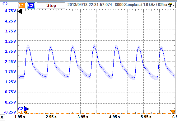
The HRM-2511E sensor is plugged into the Easy Pulse board socket J2, and a jumper is placed between second (VCC) and third (Enable) pins of J1 to turn on the IR LED. A +5V power supply is applied between the VCC and Gnd pins of the Easy Pulse board. Initially, the potentiometers P1 and P2 are set to the midpoint. The sensor is plugged into the index finger. Although the J1 header pins provides final PPG output signal, it is possible to analyze the signal at various intermediate stages through test pads TP1 and TP2. TP1 connects to the VSENSOR signal pin in the circuit diagram described in Part 1, whereas TP2 connects to the output from the Stage I amplifier (see Part 1). Connect an oscilloscope channels to TP1, TP2, AO (4th pin of J1), and DO (5th pin of J1) to observe the PPG waveforms at various stages. The following pictures show measured PPG waveforms at these test points using Digilent’s Analog Discovery tool.

Raw PPG signal at TP1 coming from the photodetector output (VSENSOR). Signal consists of a large DC component and a small amplitude of the pulsatile component

PPG signal at TP2 coming from Stage I output. The amplified signal swings about the reference voltage (Vref = 2.0V)

Final PPG output at AO pin. If the output at AO pin is found too small or saturated, adjust the gain with potentiometer P1.

Digital pulse train synchronous to heart beats are observed at DO pin. The pulse width can be varied through potentiometer P2. It’s good to set the potentiometer P2 to half-way (VR=2.5V) initially.
Summary
Easy Pulse sensor is designed for hobby and educational purposes to illustrate the principle of photoplethysmography. The new version of Easy Pulse (Version 1.1) sensor uses a transmission type sensor (HRM-2511E) that fits on finger tip and provides more stable PPG readings. The Easy Pulse V1.1 sensor provides both analog PPG and digital pulse outputs. The pulse rate information can be derived from any of the two outputs by measuring the time period of the signal. We will discuss about this more in upcoming tutorials.
Click here to buy Easy Pulse Version 1.1
|
|
Hello, I am very interested in the project and I was just wondering if there is a way to implement the circuit in MultiSim.
Thank You,
Frank
My email I’d is: ashwinsudhakar11@gmail.com
I’m interested in expanding ur project idea on mine… please send more elaborated structure of ur project to the above email…. thank-you
Please send me the code for using easy pulse sensor with arduino and display heart beat on lcd display.
please send me the code for using easy pulse sensor with arduino and display heart beat on lcd display.
please send as early as possible.
Hi
What is the exact power ratings of the easy pulse sensor circuit?I tried using 6v battery with less than 1.25A,but the signal is not obtained properly.So kindly let me know the exact power ratings of the circuit.
Thank you
Hi.. May I ask if you have a code that would allow interfacing between this sensor and CC2541/CC2540? Thx
Hi, Can this sensor give the bpm value directly without connecting it to a pc?
Thank you so much!
How to display pulse on LCD(Monitor) as graph, without PC. Just LCD(monitor) that directly connected to easyPulse? Monitor separately power supplied. Waiting for your advice)
Can i use Lm358 instead ?of MCP 6004, this is not available , or any other suitable amplifier like a LT1014CN?
thanks
Hello!
Is it possible to get the full circuit diagram? Or can you upload or mail me the original eagle files for the layout.
I will build this pulse sensor with by students at higshool.
best regards
Fridolin from austria
Hi Fridolin,
The circuit diagram is available in part 1 of this article.
http://embedded-lab.com/blog/?p=7336
Hi! my name is Alan can you tell me, What is the zener diode model you use?
thanks
Hi Alan,
I used BZX55C2V0 zener diode.
Good morning, I’m from México and I don´t know in which page can I buy the sensor HRM 25 11. Where did you buy this product?
Soy de México, y he tratado de buscar por todos lados donden venden el sensor HRM2511, pero no lo encuentro por ningún lado en Internet, solo la página alibaba pero he escuchado que no es muy confiable comprar ahí, ¿conocen de alguna otra página? Saludos 🙂
hi
when i want to install the ”Easy_Pulse_PPG_Analyzer_V1_0.exe” windows says:
‘sorry, windows can not find ‘javaw.exe’. make sure you typed the name correctly, and then try again later.’
how can i solve this problem.
please help me…
same problem how did you fix this error ??
Install JRE on your machine first. You can download it from Java website for free.
Hi, Can this sensor give the bpm value directly without connecting it to a pc?
Hi I read both version of your easy pulse and noticed that you used different number of gain and cut off in filters. I assume that it must be due to difference between output of HRM-2511E and TCRT1000, right?
Now I have HRM-2511B as my sensor, whose manufacturer is same as your HRM-2511E but it’s a reflective type sensor. I wonder if I should use Easy Pulse 1.1 or the original one to make it works. Or do you have datasheet of HRM-2511E? Because I want to compare them
I hope you’ll answer me. Thank you
You can you easily output the data from the Easy Pulse sensor and Arduino to a text file on the computer? Right now the basic code outputs it to COM3. We need to save it to a text file instead for processing. It is for a science fair experiment. Thank you!
Gus
can u pls help me to get the full pdf of this project..
Sorry 🙂
I found the answer here
Hello!
Can i connect the analog output directly to my µC adc ?
I can’t wait to see the new version
Thank you
marC:)
Hi Raj!
Is it possible to interface with pic microcontroller? is it possible to do a small project, like the first version of easy pulse?
thank you so much!
marC:)
Hi Marc,
Yes, you can use the digital output from this sensor into the original project. I am also going to write a new version of that project soon.
hiiii…. i dont understand output section … from where i get output lcd or any software required