Breadboard adapter for ESP8266 module
|
|
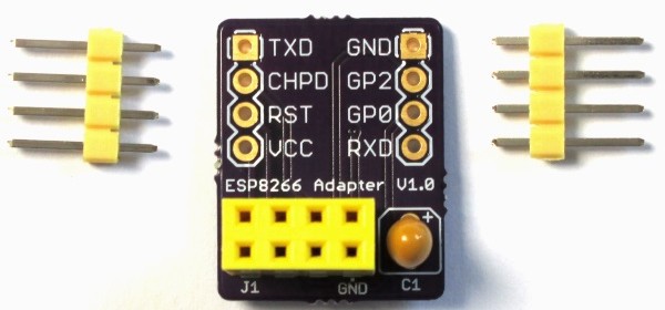
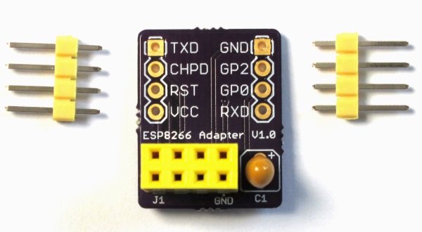
ESP8266 is an inexpensive serial-to-wifi tranceiver chip that allows to connect any microcontroller with a serial port to a WiFi network. Because of its simplicity and low cost, it is getting popular among hobbyists for building Internet of Things (IoT) applications. While there are varieties of breakout boards available for ESP8266 from the Chinese markets, the most popular one is the ESP-01 version that provides access to the ESP8266 pins through a 2×4 male header. While the headers are 0.1″ pitch, the pin arrangements are not breadboard friendly and are not labeled on board, which makes it little inconvenient for breadboarding. I have designed a very simple breadboard friendly adapter (shown below) with clear pin labels printed on the board to make prototyping with the ESP-01 module easier.
|
Buy Adapter only from Elecrow Store (recommended for international buyers)
Buy Adapter plus ESP-01 module from Elecrow Store (recommended for international buyers)
|
The adapter has a 2×4 female header to receive the ESP-01 module and a 10uF power supply filter on board. The ESP-01 module pins are accessible through two single row headers that are breadboard friendly. The Eagle design files are provided at the end of the page.
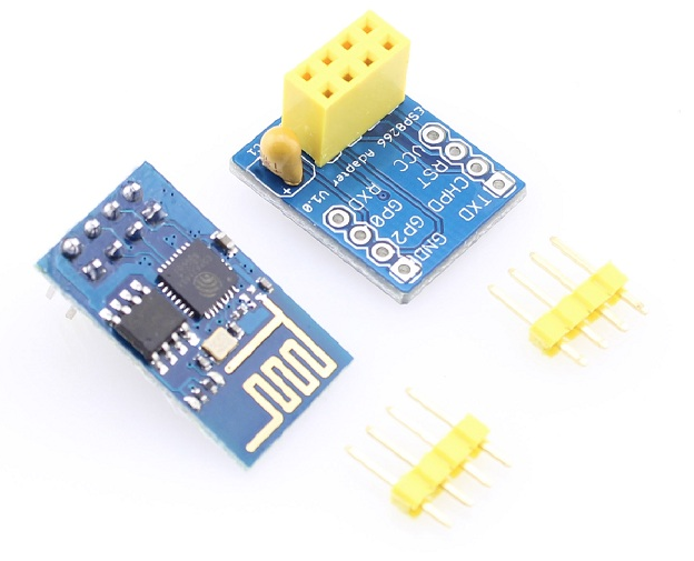
You can buy ESP-01 module and kit together from our Elecrow Store
If you are interested, you can get this adapter from our Tindie Store.
Buy ESP8266 breadboard adapter kit
|
|
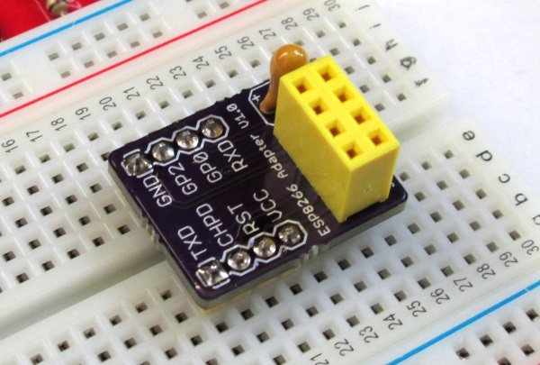
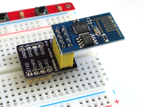
And I posted this on the next entry:
“Ideally to make this amazing gadget work, it needs instructions of some sort to show which direction the device goes into the socket.”
It was shown that way on the second photo. My seller, Tinkersphere did not actually know that important bit of trivia. All in all a good product.
Also that one is waiting for moderation….
I think a board with the wifi board over the adapter board would be nicer and take less board space.
The reason for keeping the top of the adapter clear in the current layout is to allow the users to read the pin names clearly.
Pingback: Breadboard adapter for ESP8266 module - Arduino collector blog
Raj…..I meant to use this link: http://1.bp.blogspot.com/-jrfdBSlOsZ0/VF2EM4niTgI/AAAAAAAAJeo/fQEABKaZ6ng/s1600/espboard.png
…Paul
Hi Paul,
I am considering building something like that for rapid prototyping with Arduino platform, but I have not finalized yet. The greatest concern is 300mA peak current consumption by ESP8266 module. If we source it from Arduino’s 5V on board regulator, which is rated 500mA, there won’t be enough current for users’ additional circuits. I am still working on an optimized design.
Raj…..Another great product. I’ve ordered 2.
Any chance you would consider making a version of this with an embedded 3.3 regulator so we could tap right into the Arduino 5.0V supply. Ala: http://imgur.com/a/CfMcg
Thanks….Paul