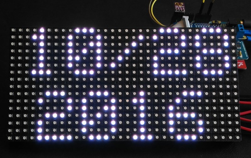
RGB matrix displays time and environmental data
|
|
Temperature, humidity, and ambient pressure are the key parameters for environmental monitoring. With the advent of MEMS and integrated multi-sensor technologies, it’s been feasible to miniaturize environmental sensors and embed them into portable electronics. BME280 is one such fully integrated environmental unit from Bosch that combines sensors for pressure, humidity, and temperature in a tiny 8-pin metal-lid LGA package of size 2.5 x 2.5 x 0.93 mm³. This article describes how to read the environmental data from BME280 using Arduino and display the data on a 16×32 RGB matrix panel using the RGB driver shield.
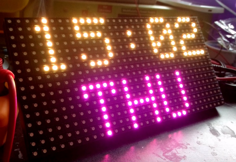
RGB matrix displaying time, date and environmental data
Things you will need
Following items are used in this project:
- Arduino Uno or any compatible board
- 16×32 RGB panel + driver shield
- 5V, 2.0A DC power supply
- BME280 sensor breakout
The 16×32 RGB LED matrix panel consists of 512 bright RGB LEDs arranged in 16 rows and 32 columns. The row and column driver circuits are built on the back side of the matrix panel. The data and control signal pins are accessible through a HUB75 (8×2 IDC) connector. It requires 12 digital I/O pins of Arduino Uno for full color control. The display panel also comes with a RGB connector shield for Arduino Uno and necessary cables for easy wiring between the RGB panel and the Arduino board. The connector shield also features the DS1307 RTC chip on board along with a CR1220 coin-cell battery holder. The I2C pins of the DS1307 chip are pre-wired to A4 and A5 pins of the shield.
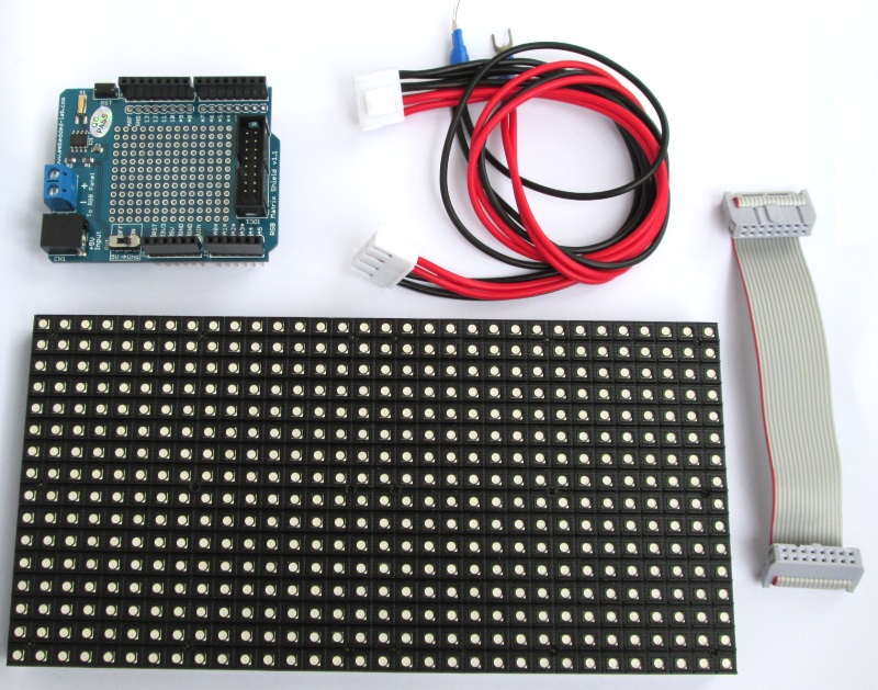
RGB matrix panel kit
Buying Links for 16×32 RGB panel kit:
From our US Tindie Store
Buy from our Elecrow Store in China
Connection setup
The RGB LED panel kit includes all the necessary cables and the Arduino Uno connector shield for an easy connection between the RGB driver pins and the Arduino I/O pins. The following picture shows the proper way of connecting the Arduino shield and the RGB panel.

Wiring the RGB panel to Arduino shield
A complete hook up guide is provided here. Basically, a 8×2 IDC cable connects the input HUB75 connector on the RGB panel’s back to the 12 pins of Arduino via the connector shield. The power supply pins of the RGB panel are connected to + and – pins of the 2-pin terminal block on the Arduino shield. The 5V DC power supply required for the RGB panel is supplied via the 2.1mm barrel jack connector on the shield.
The BME280 sensor support I2C communication. The sensor module’s data and clock pin are therefore connected to A4 and A5 pins of Arduino, respectively. I simply plugged in the the data and clock pins of the sensor breakout module into the shield headers as shown below and connected the power supply pins through jumper wires.
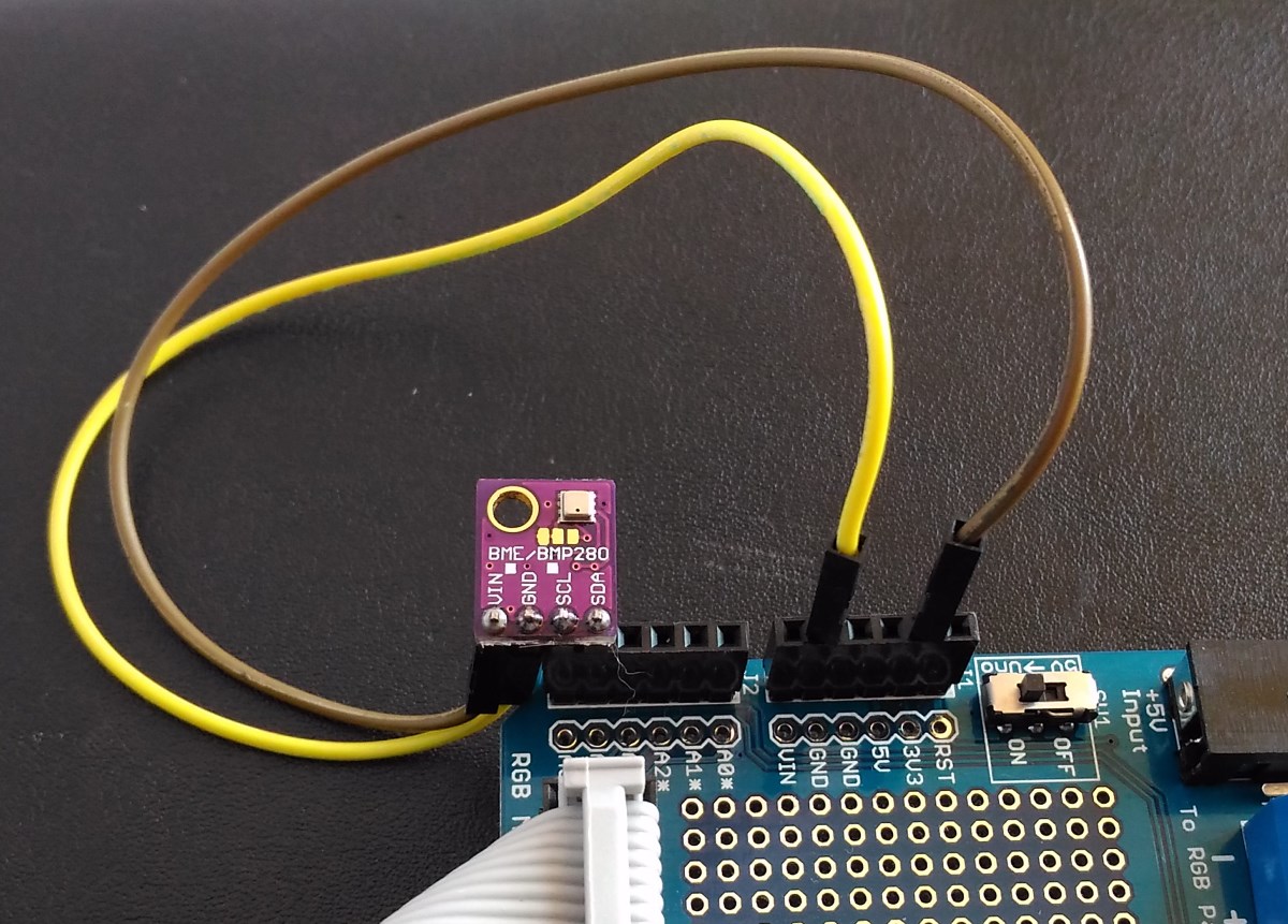
Sensor hook up
Next, you need to plug in the shield into Arduino Uno board.
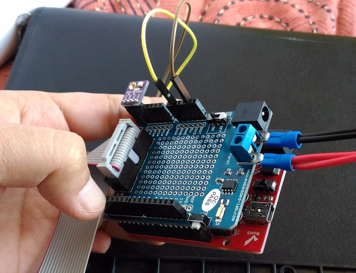
RGB connector shield plugged into Arduino Uno
Software
The Arduino is programmed to read the sensor data from BME280 and displays them on the RGB panel with different colors. The time and date are also displayed. If the DS1307 is not running at the time of programming, the date and time are set to the values corresponding to the clock settings on the computer at the time of uploading the sketch.
Arduino libraries required for this project are:
Adafruit RGB Matrix Panel library
Adafruit unified sensor library
You can download the complete Arduino code from the link below.
Download RGB16x32_BME80_DS1307RTC_TestCode
Output
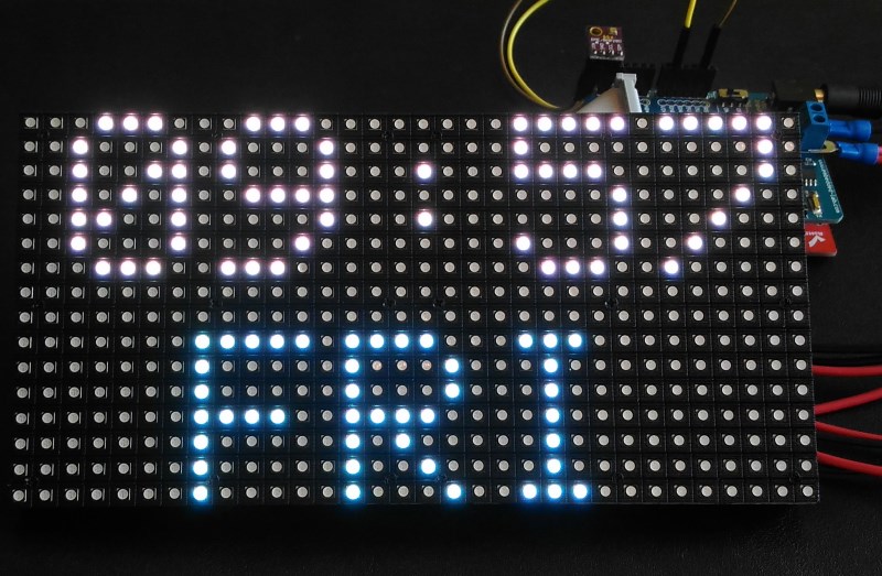
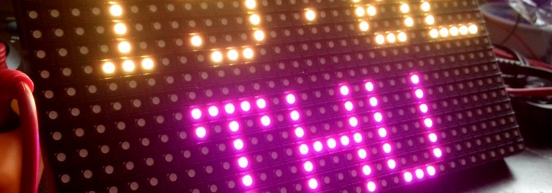
Time and Day of Week display
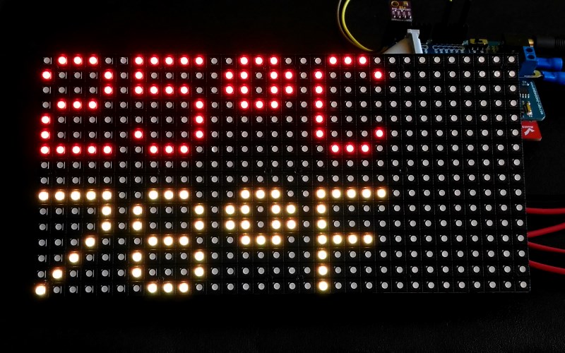
Temperature in both C and F scales
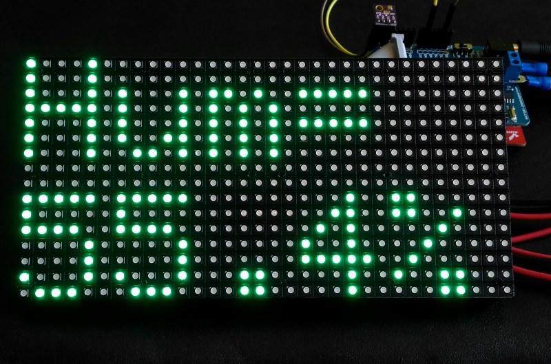
Relative humidity data
Displaying current date
|
|