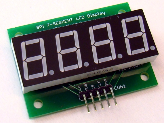
Serial four digit 7-segment LED display module
|
|
Seven segment LED displays are a very popular mean of displaying numerical information and finds application in front panel display boards of microwave ovens, washers and dryers, digital clocks, frequency counters, and many other gadgets. Compared to the LCD displays, the seven segment LED displays are brighter and provide a far viewing distance and a wide viewing angle. However, the downside is they are resource-hungry. It requires at least 12 I/O pins of a microcontroller to drive a standard 4-digit seven segment LED module. Consequently, their use with low pin-count microcontrollers (such as PIC12F series) is not practically feasible. Here’s a solution for that. The following 4-digit seven segment LED module features a serial interface that requires only 3 I/O pins of a microcontroller and provides full control of all digits and decimal points .

Four digit serial 7-segment LED display
Description
This display module is based on the MAX7219 display driver chip from MAXIM. It provides a serial interface to drive 7-segment LED displays (common-cathode type) up to 8 digits. Included on-chip are a BCD decoder, multiplex scan circuitry, segment and digit drivers, and an 8×8 static RAM to store the digit values. The segment current for all LEDs is set through only one external resistor. However, the device also provides a digital control of the display brightness (16 steps from minimum to maximum) through an internal pulse-width modulator.
Finished
The display module is powered with +5V supply applied to its Vcc pin. Data can be transferred to the display module through SPI interface. Connections are available on the board to access the required signal lines (MOSI, CLK, and CS) for communication between the SPI Master (microcontroller) and the MAX7219 chip. Data is sent in 16-bit packets (two bytes) which is shifted into the internal 16-bit shift register with each rising edge of CLK. The 16-bit packet is labeled as D0-D15, where D0-D7 contain the data, D8-D11 contain the register address, and D12-D15 are don’t care bits. D15 is the most significant bit (MSB) and is the first bit to receive. Although the MAX7219 chip can drive up to 8 digits, only 4 digits are implemented here. They are DIG0 through DIG3, arranged in sequence from the right to the left. The 4-bit addresses (D8-D11) of their corresponding digit registers are 0x01, 0x02, 0x03, and 0x04, respectively. The digit registers are realized with an on-chip 8×8 SRAM, and are addressed directly so that individual digits can be updated at any time. The following table lists the complete addressable digit and control registers of the MAX7219 device.

Register address map of MAX7219
Control Registers
The MAX7219 contains 5 control registers: decode mode, display intensity, scan limit (number of scanned digits), shutdown, and display test (all LEDs on).
Shutdown
On initial power-up, all control registers are reset, and the MAX7219/MAX7221 enters into Shutdown mode. In the shutdown mode, the display is blanked. The D0 bit of the Shutdown register (address 0x0C) must be set to bring the display to normal operation. The same bit can be cleared anytime during operation to enter back into the Shutdown mode. During Shutdown, the contents of the data and control registers are unaltered. Shutdown can be used to save power or as an alarm to flash the display by successively entering and leaving the Shutdown mode.
The MAX7219 device can be put in the Shutdown mode by sending two bytes 0x0C (address) and 0x00 (data) in sequence. Similarly, 0x0C followed by 0x01 brings it back to normal operation.
Decode-Mode
The decode-mode register (address 0x09) sets BCD code B (0-9, E, H, L, P, and -) or no-decode operation for each digit. Each bit in the register corresponds to one digit. A logic high selects code B decoding while logic low bypasses the decoder. When the code B decode mode is used, the decoder looks only at the lower nibble of the data in the digit registers (D3–D0), disregarding bits D4–D6. The D7 bit is independent of the decoder and turns the decimal point on if it is set (D7=1). For example, sending bytes 0x02 and 0x05 in sequence sets the DIG1 (second digit from the right) to display decimal 5. Similarly, 0x01 followed by 0x89 displays decimal 9 at DIG0 with its decimal point set. The following table provides the complete list of the code B font.

Code B font
When no-decode is selected, data bits D7–D0 correspond to the segment lines (A-G and DP) of the seven segment display.

No-Decode Mode Data Bits and Corresponding Segment Lines
Intensity control
The MAX7219 allows display brightness to be controlled through software by an internal pulse-width modulator (PWM). The PWM output is controlled by the lower nibble (D3-D0) of the intensity register (address 0x0A) and allows 16 brightness levels. The zero nibble value sets the display intensity to minimum, whereas all nibble bits set to 1 selects the maximum intensity level for the display.
Scan-Limit
The scan-limit register (address 0x0B) sets how many digits are to be displayed from 1 to 8. For a 4-digit display, the scan-limit register value should be set to 0x03.
Display-Test
The display-test register has address 0x0F and allows to turn all LEDs on by overriding, but not altering, the values of the control and digit registers. In order to enable the display-test mode, the D0 bit of the display-test register must be set. The same bit must be cleared to get back to the normal operation.
Interfacing with a microcontroller
The serial 7-segment LED display module can be interfaced with any microcontroller that has 3 I/O pins available. If the microcontroller features a built-in hardware SPI, then the display module can be interfaced as a SPI slave device. In that case the SPI signal lines SDO (serial data out), SCLK (serial clock), and SS (slave select) from the microcontroller can be directly connected to the MOSI, CLK, and CS pins labeled on the display module. CS is active low signal.
In case the host microcontroller doesn’t have a hardware SPI module, the interface can be implemented in software. The SPI communication starts with holding CS pin LOW and then sending 16 bits of data serially (MSB first) over the MOSI pin at the rising edge of CLK signal, and finally pulling the CS pin back to HIGH. The following example illustrates how to write a software SPI routine to drive the display module with three general purpose I/O pins of the PIC12F683 microcontroller. The program is written in mikroC Pro for PIC compiler but can be easily modified for other high-level compilers. The GP0, GP1, and GP2 pins of the PIC12F683 drives the CS, MOSI, and CLK pins, respectively, of the 7-segment display module to create a 4-digit up-counter. The counter counts from 0000 to 9999 and then reset to zero and start again.
// Define Soft-SPI connections #define CS_Pin GP0_bit #define MOSI_Pin GP1_bit #define CLK_Pin GP2_bit void SPI_Write_Byte(unsigned short num){ unsigned short t, Mask, Flag; CLK_Pin = 0; Mask = 128; for (t=0; t<8; t++){ Flag = num & Mask; if(Flag == 0) MOSI_Pin = 0; else MOSI_Pin = 1; CLK_Pin = 1; CLK_Pin = 0; Mask = Mask >> 1; } } void MAX7219_INIT() { // Disable Shutdown mode CS_Pin = 0; // CS pin is pulled LOW SPI_Write_Byte(0x0C); // Select Shutdown register SPI_Write_Byte(0x01); // Set D0 bit to return to normal operation CS_Pin = 1; // CS pin is pulled HIGH // Set BCD decode mode for digits DIG0-DIG3 CS_Pin = 0; // CS pin is pulled LOW SPI_Write_Byte(0x09); // Select Decode Mode register SPI_Write_Byte(0x0F); // Select BCD mode for digits DIG0-DIG3 CS_Pin = 1; // CS pin is pulled HIGH // Set display brighness CS_Pin = 0; // CS pin is pulled LOW SPI_Write_Byte(0x0A); // Select Intensity register SPI_Write_Byte(0x0a); // Set maximum brightness CS_Pin = 1; // CS pin is pulled HIGH // Set display refresh CS_Pin = 0; // CS pin is pulled LOW SPI_Write_Byte(0x0B); // Select Scan-Limit register SPI_Write_Byte(0x03); // Select digits DIG0-DIG3 CS_Pin = 1; // CS pin is pulled HIGH // Enable Display-Test CS_Pin = 0; // CS pin is pulled LOW SPI_Write_Byte(0x0F); // Select Display-Test register SPI_Write_Byte(0x01); // Enable Display-Test CS_Pin = 1; // CS pin is pulled HIGH Delay_ms(1000); // Disable Display-Test CS_Pin = 0; // CS pin is pulled LOW SPI_Write_Byte(0x0F); // Select Display-Test register SPI_Write_Byte(0x00); // Disable Display-Test CS_Pin = 1; // CS pin is pulled HIGH } void Display_Counter(unsigned int j){ CS_Pin = 0; // CS pin is pulled LOW SPI_Write_Byte(4); // Send thousands digit SPI_Write_Byte((j/1000)%10); CS_Pin = 1; // CS pin is pulled HIGH CS_Pin = 0; // CS pin is pulled LOW SPI_Write_Byte(3); // Send hundreds digit SPI_Write_Byte((j/100)%10); CS_Pin = 1; // CS pin is pulled HIGH CS_Pin = 0; // CS pin is pulled LOW SPI_Write_Byte(2); // Send tens digit SPI_Write_Byte((j/10)%10); CS_Pin = 1; // CS pin is pulled HIGH CS_Pin = 0; // CS pin is pulled LOW SPI_Write_Byte(1); // Send ones digit SPI_Write_Byte(j%10); CS_Pin = 1; // CS pin is pulled HIGH } unsigned short i; unsigned int counter = 0; void main() { TRISIO=0b00001000; // GP3 is input only CMCON0 = 0x07; ANSEL = 0x00; MAX7219_INIT(); // initialize max7219 do{ for (counter=0; counter<10000; counter++) { Display_Counter(counter); Delay_ms(1000); } }while(1); } |
The PIC12F683 microcontroller runs at 4.0 MHz internal clock and MCLR is disabled. In the picture below, the tiny PIC12F683 board is from iCircuit Technologies.

4-digit UP-counter using PIC12F683
The LED display module can also be interfaced with Arduino board using the LedControl library.

Interfacing with Arduino
Summary
This MAX7219 based LED display module allows you to interface a 4-digit 7-segment LED display to low-pin count microcontrollers using only three I/O pins. It gives you full control of all digits, decimal points, and the display brightness.
For purchasing an assembled and tested version of this display module, visit our Tindie Store.
Revision 1 (12/15/2012)
The PCB has slightly been revised recently. Everything remains the same except there are two header connectors available now. One for interfacing the display with a microcontroller and other for cascading multiple displays. New PCB is shown below.

SPI 7-segment display kit (four digit)

Assembled display board
Here’s the circuit diagram of this display board.

Serial 4-digit display circuit
Revision 2 (02/20/2013)
The new revised version has following improvements:
- High quality 0.40? display (LTC-4727JS) with bright yellow light emitting diodes
- Four digits, decimal and colon segments
- Round PCB corners

- Rev 2: SPI seven segment LED display
The new version uses all surface mount components.

Revision 3 uses SMT components
More details on the new board can be found here. You can buy an assembled board for $12.50 on Tindie. International buyers can also buy this from Elecrow, which ships this item world-wide at a much cheaper shipping cost.
|
|
Pingback: High-voltage seven segment LED display driver with SPI interface -Use Arduino for Projects
I realize this is article is quite a few years old now, but if you are still around, I wanted to thank you for taking the time to post it. I was having some sequence issues in learning this chip. (PEBKAC entirely after seeing it work).
Thank you.
Bob
i m using common anode serial-3-digit-seven-segment-led-display -LTC4624 how to select a digit pls help me
its very useful thanks
Pingback: MAX7219 を使えば桁数の多いセグメントLEDを簡単にSPI化できるのか – OnBoard PRESS Japan
Is there any way to get the PCB layout and/or hole measurements? I want to mount these modules (the two layer ones) on a bigger board and need to know the pin-placement and hole spacing.
Can you write the code in mikrobasic for pic,please.
Hi…thanks for the clear explanation. Can you please help adapt the SPI code, especially the SPI_Write_Byte function for MPLAB XC8 compiler? Thank you.
How it can be done without MAX7219? Please guide
how far it can support?
Hi
I am interested in this product, but I have problems with the code.
Can you write this code in C language for AVR:
void SPI_Write_Byte(unsigned short num){
unsigned short t, Mask, Flag;
CLK_Pin = 0;
Mask = 128;
for (t=0; t<8; t++)
{
Flag = num & Mask;
if(Flag == 0) MOSI_Pin = 0;
else MOSI_Pin = 1;
CLK_Pin = 1;
CLK_Pin = 0;
Mask = Mask >> 1;
}
}
Thanks in advance
Feb
Is it possible to use 2 x 2-digit displays, instead of the 4-digit display?
I need to control 20 x 2-digit displays.
Thanks
Martin
Hello R-B,
I need to ask you something, MikroC has directly
Soft_SPI_Init
Soft_SPI_Read
Soft_SPI_Write
Software library routines to be used directly… why you have used ? SPI_Write_Byte (your own made) function ?
can’t we use mikroc inbuilt Soft_SPI_Write ?
Please reply.
Of course you can use it too.
Can i use SPI_Write_Byte to write to slave device you made here in other same projects with different hardware ?
Thanks
@Rubina
How it can be done without MAX7219? Please guide.
adnan_khattak6@hotmail.com
It can be done without using MAX7219 also…!
Can you explain more about the following codes:
void SPI_Write_Byte(unsigned short num){
unsigned short t, Mask, Flag;
CLK_Pin = 0;
Mask = 128;
for (t=0; t> 1;
}
}
Can I buy just the PCB from you, I have all the components. I’m looking for around 5 PCB’s
Thanks
Kevin,
I can send you 5 PCBs for $25 including shipping within the continental US.
I am thinking in a solution like your board:
http://embedded-lab.com/blog/?p=4935
but using Attiny2313 (or similar) instead MAX7219 (more expensive).
Sparkfun use an Atmega, but is a waste of its capabilities.
http://www.sparkfun.com/products/9765
MAX7219 isn’t that expensive if you order on eBay. It’s about $0.50 per piece.
See http://youtu.be/OQwlK8JtTx4 for a simple demonstration.
Works like a dream.
I adapted code for the Picaxe 08m device also, see http://www.picaxeforum.co.uk/showthread.php?20572-MAX7219-Serial-LED-Driver&p=209167&viewfull=1#post209167
Evan,
Thanks a lot for adapting the code with PICAXE platform.
This is a cool product!
Thanks, Dany.
Pingback: Serial four digit 7-segment LED display module controlled by Arduino / Cooking Hacks Blog
Pingback: La semana en links (8/05/2012) | Automatismos Mar del Plata