DIY Geiger Counter using 555
Geiger counters are used to detect beta particles and gamma rays radioactive emissions. The counter consists of a tube filled with an inert gas such as helium, neon, or argon at low pressure, to which a high voltage is applied. The tube becomes conductive of electricity when it is impacted by a high-energy particle or photon. Tanner_Tech‘s Instructable shows how to build the simplest 555 timer based DIY Geiger counter using minimal electronic components.
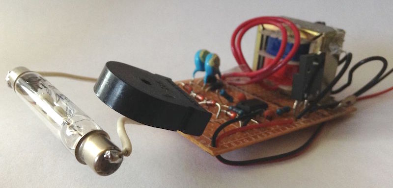
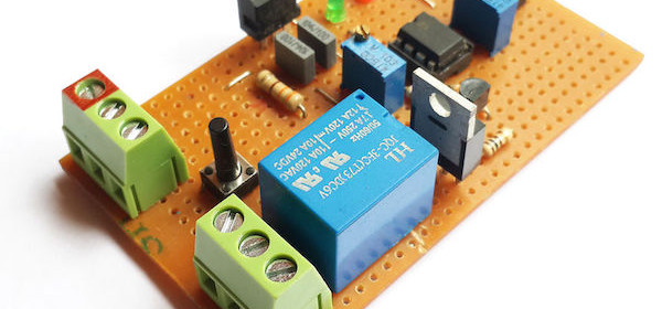
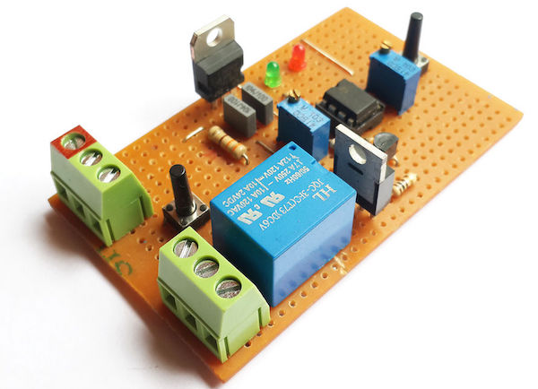
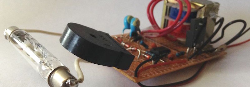
Geiger counter using 555 timer
Tanner_Tech‘s design uses 555 timer IC as an astable multivibrator to drive a step-up transformer through a MOSFET in order to generate the high voltage required for the Geiger tube. A piezo element placed in series with the Geiger tube acts as a detector, which clicks every time the ionization event occurs inside the tube due to high energy particles.
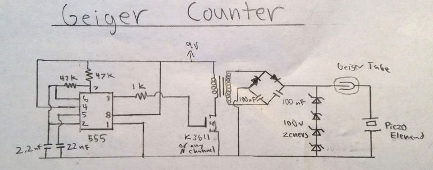
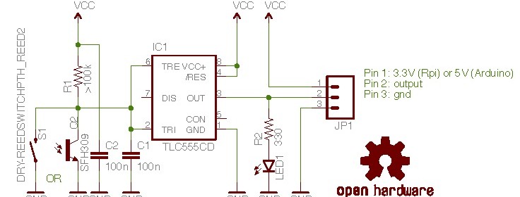
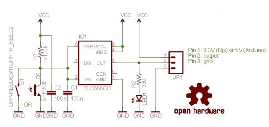
Circuit diagram of 555 timer based Geiger counter
Following video shows this device working.
Too make this Geiger counter work, there needs to be two parts of this circuit; the high voltage power supply, and the detector circuit. In the diagram above, the high voltage circuit consists of a 555 timer driving oscillator driving a transformer. The 555 timer generates a square wave that, through a resistor, turns on and off a MOSFET transistor. This MOSFET drives a small step up transformer. The output of the transformer is then fed into a voltage doubler where the voltage is boosted to about 500 volts. Then, the voltage is regulated through a series of 4 100v zener diodes to the Geiger tube’s recommended 400 volts.
For the detector circuit, the Geiger tube’s anode is wires directly to the 400 volt power supply. In between the cathode of the tube and ground, I placed a piezo electric element. This converts the small current flow from the Geiger tube to a audible click.