Search Results for: test circuit software

chipKIT Tutorial 6: Inter-Integrated Circuit (I2C) communication

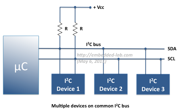
I2C or IIC (Inter-Integrated Circuit) is a simple bidirectional serial interface, which requires only 2 signal lines for data transfer. It was originally developed by Philips in 1980′s to provide easy on-board communications between a CPU and various peripheral chips in a TV set. Today, it is widely used in varieties of embedded systems to connect many low speed peripherals, such as external EEPROMs, sensors, LCD drivers, port expanders, real-time clocks, etc, to the host microcontroller. In this tutorial, we will explore the chipKIT Wire Library for establishing an I2C communication link between the chipKIT Uno32 board and two I2C

Read more

Digital logic probe for troubleshooting TTL and CMOS circuits

A logic probe is considered as a stethoscope for engineers and technicians for debugging digital logic circuits that consists of logic gates, memories, registers, etc. A digital multimeter (DVM) can also be used for such analytical purposes but it gives you the numeric value of the voltage at a point instead of the logic state. Depending on whether the circuit is based on TTL or CMOS components, the voltage levels for logic 0 and 1 could be different for each family. DVM users, thus, have to calculate logic levels from the measured voltages, which consumes time and delays the troubleshooting procedure.

Read more

In-Circuit Debugging of PIC microcontrollers

An In-Circuit Debugger (ICD) is a very powerful and effective tool for real-time debugging of a microcontroller-based system at hardware level. It allows you to run, halt and single step the program while the target microcontroller is embedded in the actual circuit. Once halted, the program variables, Special Function Registers (SFRs), RAM and EEPROM locations can be examined and modified in real-time, thus assists the designer in debugging the firmware and hardware together. In this article, I am going to describe the In-Circuit Debugging technique in PIC microcontrollers, and demonstrate the debugging procedure with a test project using the PIC16F887 microcontroller. Although the operation of

Read more

Lab 14: Inter-Integrated Circuit (I2C) communication

I2C (Inter-Integrated Circuit) is a short distance serial interface that requires only 2 bus lines for data transfer. It was invented by Philips in 1980’s, originally to provide easy on-board communications between a CPU and various peripheral chips in a TV set. Today, it is widely used in varieties of embedded systems to connect low speed peripherals (external EEPROMs, digital sensors, LCD drivers, etc) to the main controller. In this experiment, we will cover an overview of I2C protocol, its implementation in PIC microcontrollers, and the method of connecting single and multiple devices on a common I2C bus. We will

Read more

Microcontroller based Diode and Bipolar Junction Transistor (BJT) tester

Introduction Most of the digital multimeters these days have built-in features for testing diodes and sometimes transistors. The purpose of this project is to demonstrate a simple way to construct a testing device for diodes and bipolar junction transitors (BJTs) using a microcontroller. The testing algorithm is based on a simple fact that a working PN junction conducts current in only one direction. A PIC16F688 microcontroller is used in this project that switches the bias voltage across the PN junctions of diode and transistors, and determines if a particular junction is normal, open or short. Theory The logic behind testing

Read more
« Older Entries