A brief overview of Allegro ACS712 current sensor (Part 2)
|
|
In the first part of this discussion, the features of ACS712 device were briefly discussed. Now we will use that theory to implement the ACS712 sensor to make a simple DC current meter. The analog output voltage from the sensor is measured through an ADC channel of the PIC16F1847 microcontroller. A voltage to current conversion equation will be derived and implemented in the firmware of the PIC microcontroller and the actual load current will be displayed on a character LCD.
Experimental circuit setup
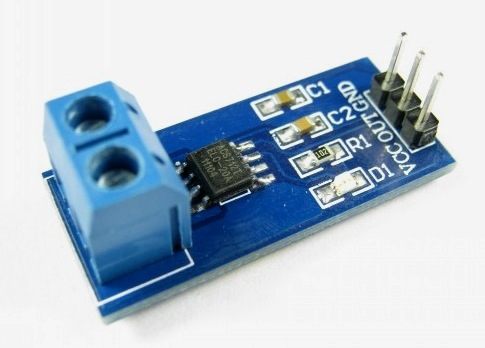
We are going to setup a test experiment to demonstrate the use of ACS712 to measure a DC current. I am using an ACS712-05B breakout module (you can find them cheap on ebay) for this purpose. It has got a 1 nF filter capacitor connected between pin 6 and ground, a 100 nF decoupling capacitor between power supply lines, and a power on LED soldered on the board. The power supply and output lines are accessible through header pins on one side, whereas, the current terminals are connected to a 2-pin terminal block on the opposite side, as shown below.
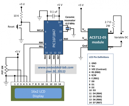
The experimental circuit diagram of the DC current meter is shown below. A 2.7 ? (rated 2 Watt) resistor is connected in series with the current terminals and a varying dc voltage is applied to vary the current through the resistor and the current path. The output of the sensor module goes to AN0 (pin 17) ADC channel of the PIC16F1847 microcontroller. A 16×2 character LCD is used to display the measured current output.
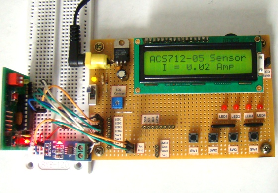
I am using my PIC16F1847 breadboard module along with the Experimenter’s I/O board to demonstrate this experiment.
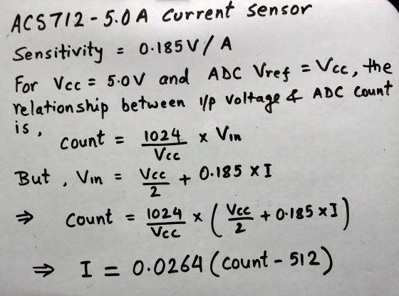
The microcontroller uses the supply voltage (+5V) as reference for A/D conversion. The digitized sensor output is processed through software to convert it to the actual current value. The mathematics involved in the process is described in the white board below.
Important note: The calculations shown above considered supply voltage Vcc = Vref = 5.0 V. Interestingly, the final equation relating I and Count remains the same even the power supply fluctuates. For example, suppose Vcc fluctuates and becomes 4.0 V. Then, the sensitivity of the ACS712-05B also changes to 0.185 x 4/5 = 0.148 mV. If you repeat the above calculations with Vcc = Vref = 4.0 V and sensitivity = 0.148 mV, you will end up with the same equation for I and Count. This was possible because of the ratiometric output of the ACS712 sensor.
The equation clearly tells that the current resolution for this setup is 26.4 mA, which corresponds to count 513, one count higher than the zero current offset. Therefore, this kind of arrangement is not suitable for measuring low current. You need an external Op-Amp circuit to enhance the resolution and be able to make more sensitive current measurement. If you are interested on that, you can visit Sparkfun’s ACS712 Low Current Sensor Breakout page that provides a circuit diagram for such an arrangement.
Software
The current-Count equation described above is implemented in the firmware of PIC16F1847 to compute current from digital count. The result is finally displayed on the LCD with a precision of two decimal places. The following software is written in C and compiled with the mikroC Pro for PIC compiler from mikroElektronika.
/* Project: Use of ACS712 sensor for DC current measurement MCU: PIC16F1847 running at 4.0 MHz using external resonator and MCLR is enabled Written by: Rajendra Bhatt (www.embedded-lab.com) Jan 22, 2012 */ // Define LCD connections sbit LCD_RS at RB0_bit; sbit LCD_EN at RB1_bit; sbit LCD_D4 at RB4_bit; sbit LCD_D5 at RB5_bit; sbit LCD_D6 at RB6_bit; sbit LCD_D7 at RB7_bit; sbit LCD_RS_Direction at TRISB0_bit; sbit LCD_EN_Direction at TRISB1_bit; sbit LCD_D4_Direction at TRISB4_bit; sbit LCD_D5_Direction at TRISB5_bit; sbit LCD_D6_Direction at TRISB6_bit; sbit LCD_D7_Direction at TRISB7_bit; // End LCD module connections void Display(unsigned int num){ char temp[] = "I = 0.00 Amp"; temp[4] = num/1000 + 48; temp[6] = (num/100)%10 + 48; temp[7] = (num/10)%10 + 48; LCD_Out(2, 3, temp); } char message[] = "ACS712-05 Sensor"; unsigned int ADC_Value, Factor; unsigned long temp; main(){ ANSELA = 0x01; // PORTA.0 is analog TRISA = 0b00100001; // RA5 and RA0 are inputs ANSELB = 0x00; // PORTB pins are all digital TRISB = 0x00; // PORTB pins are all output Lcd_Init(); Lcd_Cmd(_LCD_CLEAR); // CLEAR display Lcd_Cmd(_LCD_CURSOR_OFF); // Cursor off Lcd_Out(1,1,message); Factor = 264; // To conver Count into current do{ // Read multiple samples for better accuracy ADC_Value = ADC_Read(0); ADC_Value = ADC_Value + ADC_Read(0); ADC_Value = ADC_Value + ADC_Read(0); ADC_Value = ADC_Value/3; temp = (ADC_Value-512)*Factor ; ADC_Value = temp/10; Display(ADC_Value); Delay_ms(1000); } while(1); } |
Output
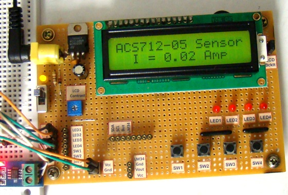
At zero input current, the ACS712 output should be ideally Vcc/2, which is equivalent to an ADC count of 512. A drift of 4.9 mV in the output voltage of ACS712 results in an offset of 1 LSB in the A/D conversion (for Vref = 5.0V, resolution of 10-bit ADC is 5V/1024 = 4.9 mV). Interestingly, one LSB is equivalent to 26mA of current for ACS712-05B. The drift of 4.9 mV or more in the zero current output voltage is considered likely to happen, which is reflected in the output shown on the LCD. I have seen the ACS712 output for zero input current fluctuating between 512 and 513 ADC counts. If it is 513, the displayed current would be 0.02 A. So it is always better to take multiple ADC measurements and then take their average.
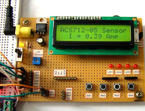
When the variable DC is set to 1.0 V, the current through the 2.7 ? resistor should be 370 mA. The measured value is 390 mA, which is off by 1 LSB.
This concludes the discussion on the ACS712 current sensor. However, one concern is still not addressed. How would you measure an AC current with the ACS712 sensor? Keep in mind that the ACS712 sensor provides an instantaneous output corresponding to the current flowing through the conduction terminals. If the current flow is in positive direction (from pins 1 and 2 to pins 3 and 4), the sensitivity of the device is positive, and the ACS712 output voltage rises above Vcc/2. But if the current changes its direction, the sensitivity will be negative and the output of the ACS712 decreases below Vcc/2. This means, for an AC current, the 10-bit ADC output measured by the microcontroller oscillates about 512 counts. Therefore, the microcontroller needs to sample the sensor output fast enough so that the RMS value of the current can be computed from them.
References
ACS712 FAQ from Allegro website
|
|


its very unreliable when using arduino with usb, because codes take ideal 5 volts into consideration, while in real world this dosent happen, and thus the readings fluctuate. I have tried and made this work, now all aspects of sensors and formulas are taken from current voltage, which are measured by secret arduino voltmeter.
http://inoace.com/blog/acs712-current-sensor-practical-formula/
Thanks a lot for this formula
“0.185 x 4/5 = 0.148 ”
data sheet has quite tough one i didnt understood. Attaching arduino via usb, voltage fluctuates quite a bit. and thus cause fluctuations in sensor readings. Here is my code, it averaged and used current vcc to calculate all readings, thus eliminating fluctuations
http://inoace.com/blog/acs712-current-sensor-practical-formula/
thankyou for sharing knowledge, Love from Pakistan
Appreciable Explanation Thanks
I want to measure AC current using ACS 712 with arduino. Can someone help me out regarding circuit diagram. Is ACS712 output dirctly given to ADC of arduino or some circuitry is require??
Sir,
What does the ’48’ in the coding refer to ?
How can i measure the dc current with acs 712 5A with arm cortex microcontroller because the voltage reference of adc chanel is 3.3 v while the VCC supply is 5v.
Please help me.Thanks everybody so much.
My email: ductrinheiu@gmail.com
Excuse ignorance but did not understand where he withdrew the resolution value to 0.0264!
The correct would not Res = 0.185V / 5A = 37mA ?? and not 26,4mA ??
Hello,
I will try to build this circuit with PIC18F4550. Is that possible? Secondly, If you have circuit schematic in proteus, could you share?
Where is the value of 0.0264 obtained?
Solving the last equation for I and using VCC=5.0V.
Excuse ignorance but did not understand where he withdrew the resolution value to 0.0264!
The correct would not Res = 0.185V / 5A = 37mA ?? and not 26,4mA ??
The white board math is wrong. Should be I = .0053(count – 512)
Math is correct, sorry. vcc = 5V.
Hi,thanks for this really cool project.Just amazing.
I am really interested to know that which CAD software do you use to generate and design these awesome looking schematics.I mean they look very neat and clean and pretty awesome than that generated by other CAD tools like EAGLE,etc.
Please do share the CAD schematic tool you use and if you also have a tutorial for that will be amazing.
Thanks
can u give us some exampol for current sensing with opamp ( LM358 OR LM 324 etc ) ?
How to maeasure current in a 230v ac circuit
Thanks for posting this project. It’s really awesome.
HI,
in “Mathematics involved in ADC conversion”, where does the number 1024 comes from?
If it is from a 10 bit ADC of the microcontroller, shouldn’t it be 1023?
cảm ơn anh(thanks).
I successfully calculated +ve current but what is precise formula for calculating -ve current??
I want to enter a sinusoidal source. how please?
R-B,
ACS712 pin number 6 is for filter Cap.
Q1:What if I close a short-circuit between pin 6 and 7(Vout)?
Q2:What if I put no Cap at pin 6?
Dear all,
i need measuring current AC line 220V, Vout of acs712 = vcc/2, when VCC drop or increase may Vout fluctuation too. please help me how to resolve in order to make the Vout constant when VCC fluctuation. please give me some schematic to my email aa_elko@yahoo.com. many thank’s for your help.
Another one best project.. really awesome
Hi my problem is some like this, I am measuring current through resistance
one point of resistance is connected to 24V supply and resistance value may vary from 500 ohm to 1000 Mohm.
when i connect 5.6 Mohm resistance and put 24V on its one terminal than at other terminal i received 14V its too high to read on controller please help me with some circuit making 0-24V in range of 0-5V dc. one thing more current is not enough a doubler is used to create 24 volt resistance divider is not working in this condition i already practically checked.
I would like to get the hex file for PIC16F84A. It would be very thankful.
thank you very much ….
how can apply this project with AC current ?
Pingback: 8051
R-B, I think at the last line of your calculation which is
(I=0.0264 (count=512)) must be (I=0.0264 (count=513)) to be
the calculation is correct.
Thanks.
ADC_Value = ADC_Read(0);
ADC_Value = ADC_Value + ADC_Read(0);
ADC_Value = ADC_Value + ADC_Read(0);
ADC_Value = ADC_Value/3;
it give us men value or average value
I would be more comfortable in answering to your question if you would explain to me the difference between the mean and the average of three numbers.
Pingback: Electronics-Lab.com Blog » Blog Archive » A brief overview of Allegro ACS712 current sensor (Part 1)
Nice tutorial.
Do you know about any non-allegro alternative product?.
I noticed on the next to the last image the current is shown to be .39A. Yet, the article calls it out to be 39mA. Would not .39A be 390mA?
Kyle,
That’s true. I made the corrections. Thank you.
Another one best project.. really awesome 🙂