A very simple IR remote control switch for an electrical appliance
|
|
This project describes a technique of adding the remote control feature to an electrical appliance. The goal is to construct a black box where you can plug-in your 120V AC appliance (it can be easily modified for 220 V mains supply too) and control the ON and OFF operations with a TV or DVD remote that uses modulated infra-red (IR) pulse train of 38 KHz frequency. I did this project for my wife who studies late at night on her bed and later feels tired to stand up and turns the light off. Now she does it from bed with the TV remote. The good thing about this project is that it does not use any microcontroller and is only based on the CD4017 decade counter IC.

IR toggle switch for an electrical appliance
Circuit diagram
The original circuit diagram for this project was published in the May 2005 issue of the Electronics For You magazine. The circuit diagram below is mostly the same. It uses a TSOP1738 IR receiver module at the input side to receive the 38 KHz frequency IR pulses from the remote control. Under normal condition, the output pin of the IR module is at logic High, which means the transistor T1 (BC557 PNP) is cut-off and its collector terminal is at logic Low. The collector of T1 drives the clock line of the CD4017 decade counter.
Now lets see what happens when somebody faces a TV or DVD remote towards the TSOP1738 and presses any key on it. The TSOP 1738 module receives the train of 38 KHz IR pulses from the remote, that makes its output to oscillate too. These pulses are inverted at the collector of T1, which finally go to the clock input of the decade counter. The arriving pulses could increment the CD4017 counter at the same rate (38 KHz), but because of the presence of the RC filter circuit (R1 = 100K, C1 = 10 uF) between the collector and the ground, the train of pulses appear as a single pulse to the counter. Thus, on each key pressing, the CD4017 counter advances only by a single count. When the user releases the key, the C1 capacitor discharges through the R1 resistor, and the clock line is back to zero. So every time the user presses and releases a key on the remote, the CD4017 counter receives a single pulse at its clock input.

IR remote switch
Initially, when the circuit is just powered on, the Q0 output of the CD4017 decade counter goes high. The counter increments for each low-to-high going pulse arriving at its CLK pin (14). When the first pulse arrives, Q0 goes Low and Q1 is turned High. This activates the relay and the AC appliance connected to it is turned on. The status LED connected to Q1 also glows to indicate the appliance is switched on. When the user presses a key again, the second pulse arriving at the CLK line increments the counter by 1. This makes Q1 back to Low (which means the relay is deactivated and the appliance is turned off) and Q2 is pulled High. Since Q2 is wired to the Reset input, the second key press actually brings the CD4017 IC back to the power-on-reset conditions with Q0 High. Thus, it basically operates as an ON/OFF toggle switch controlled with any key of an infrared remote.
The power supply for the circuit can be derived from the mains AC itself using a step down transformer and a bridge-rectifier circuit. For +5V power supply, the LM7805 regulator IC can be used as shown below.

Power supply circuit
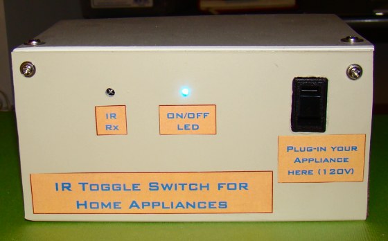
I have enclosed the circuit board with the power supply inside a wooden box as shown in the pictures below. The electrical appliance to be controlled can be powered from the AC outlet at the front side.

Circuit board and power supply enclosed within a wooden box

Finished project with AC socket at the front side

Testing the finished project with a TV remote
This was a very simple and fun project to do. If you are thinking about making this device for yourself, be careful with the direct 120 V AC lines used in the project.
|
|
sir i make it but it is very slow when i press botton approximately 10 time so the light is on
how can i maKe it fast it my school project so please tell me
Hi,
Unfortunately, like many circuits using a similar approach to toggle a lamp, or a fan for example, the above circuit can’t be used in the same room where you have a TV, DVD or any other remotely controlled device. Let’s face the facts, it would be very annoying to see the lamp or the fan, turning on and off, each time you change your TV channel or adjust the volume, no ?
And by the way, the IR beam can’t me concentrated in such a way that the IR beam is seen only be the TV and not by your circuit. Presented like this, the usefulness of this circuit in a living room is close to none.
Anyhow, have fun with that intermittent lamp/fan if you plan to go ahead anyhow.
What if we want to operate 220 v rated induction motor of air cooler. N want to modify the given circuit for 3-5 channels .
Plz give more description
Sir how to control more than one electrical good….?
Sir can u plz tell me how universal IR remote control designed for air conditioner
I make it but one problem..when CFL bulb is on then it work….but when CFL bulb is off then it doesn’t work…..
Not working this project help me
I asseble all parts
Check your circuit..
Dear Sir,
Is there any compact circuit diagram which can help to make a remote control switch for controlling fan speed and light using the same circuit?
Regards
i have made this circuit. But it is getting OFF after few minutes. Where can be the fault in connection or is it component problem ?
I have also
it work but if power is on the light does not off and press the button again the light blinking
How can I use this circuit to operate 2 or 3 appliances ? plzz tell me..
For that, you need to decode the data coming form the remote’s IR Transmitter using microcontroller. I have written one article on this decoding of IR data of IR remote.
http://techiesms.blogspot.in/2016/02/analyze-any-ir-protocol-with-just-you.html
How can I use this circuit to operate more appliances ? plzz tell me..
Please sir what part shuld i conect my +5 volt is on the relay or the one on IC?. My statuz led is not showing and my remote is not responding , but once i connect the circuit to a source the relay wil triga and remain on and the circuit refuses to respond to the remote control please what can i do .thank u inadvance sir.
it work but if power is on the light does not off and press the button again the light blinking and how can I use to more than one chanel
Bilkul tumhari tarh mera bhi cicuit aisa he kr rha h…agr tumhe koi solution mila ho to pls mujhe bata do…
good project, I will try it for my house gate light.
This circuit is already in on condition. Give me a solution for it.
The circuit works fine, but I’m having a small issue, the circuit can be turned on via remote control from the far distance but to turn off the remote control has to be near the sensor that is around 10 inches and also some times it turns on by itself.
great work!!
it is working more than 100%.
thanks for your service.
its not working, its not counting one signal at a time.
Sir what ic can be used as altrnate of CD4017?? Sir have there any??plz help me, bcZ CD4017 is not avilable in Bagerhat.
You may use 4027 in place of 4017
Can I use another universal IR reciver
can i use a 12v relay
No because we are getting 5 volt regulated supply
Yes you can use, but remember you have to give supply of 12v to the relay then after that it toggle switch,you have like this:- take a power supply of 12v and use 7805 ic for the whole circuit and then after that give a direct supply of 12v to relay and in this way you can use that 12v relay. Good luck..
helo sir,
i have done ir remote switch circuit. dc part is working. ac part is not working plz tel what to do?
can u tell how there are two +5v connection(one into the ic and another in the relay)..i am not understanding plzz help..
hello sir,
is this circut able to work on 220v supply ?
reply soon .
Sir,
Can I use 12V relay instead of 5V/6V…pls reply fast…. It is for my project
can I use 6v battery for this circuit ? (or) Is there any other alternative to provide 5V supply?
use mobile charger
Thank you very much sir for giving and explaining a very good circuit. It will help me in my Engineering concepts and projects. Sir I want to know the resistance of relay. And can I use this circuit with 6V DC supply instead of 5V.
And if I can then what will be resistance value of 6V relay that I have to use.
100 OHMS is the resistance of relay
U can use an 5v voltage regulator with 6 volts supply
i was able to construct mine but having serious challenge with my remote device not responding to the ir module. your immediate help will be appreciated….
hi sir i need more about working principal of that circuit.how the signal it came from remote up to lamp controlled
thanks.
hi sir i need more about working principal of that circuit
Can i make this ckt to control the whole power board. like i want to control fan, ac, tubelight etc from single ckt. is it possible? if it plz mail me the ckt manisha.bansal9012@gmail.com as soon as possible
dear sir,
i have to control 3 light and fan from same TV remote using different keys.
what modifications should have to do in that circuit.
good work
Hello, Is it possible to modify this so resets automatically after a set time of 15 minutes?
Thanks,
Dan
Hi sir!
I have almost completed my project but i’m anble to give connection to Relay, so can you please solve my problum, my mail is prashant.ps74490@gmail.com
THANKS!
SIR there is 8 pins in relay but we have to give connection in only 4 pins in which pin I should give that is my problem
how can this circuit be modified for 220V supply…..????? pls replyy…. 🙂
Hi There,
Any success on making the same circuit to control 220V home appliances?
Can you please help me out and give me the circuit diagram for 220V or at least let me know what are the changes I have to make in this 120V circuit to make it work for 220V appliances.
my email is adeelnav@yahoo.com
Best regards,
David
Ajay,
Any success if you found the solution for what you are looking for? I am also seeking the same.
Thanks in advance!
For using this circuit with 220V AC, replace the 120V/9V transformer with 220V/9V transformer. Then it should work with 220V line.
Uncle plzz sort out my problem…..my problem is i bought a 220v to 6v transformer and without relay the led was indicating perfectly but After installing the relay the transformer made a sound and it repaired.there was no voltage coming out from my transformer. i bought another one and it also went away after making a buzzing sound..i gave the parallel connection to relay and transformer from 220v…..should i do some change….i am really annoyed and i am very sad that i couldn’t make this…..Plzz help me… i am a student of class 9…..
good day sir. you have a good ckt here. 🙂 I do have one request, may I have a copy of the PCB Layout or diptrace file? thanks for your kind consideration sir. (: kindly send it to my email, joab.torres@ymail.com…thanks!
Hi , I just made this circuit and it works but there’s an issue. When I connect it to any regulated power supply (Eg: 500mA Transformer cercuit with LM317 -Set to 5 V) it does not work and the relay switches on and off only once. But the same cercuit works perfectly fine when using 4 AAA Cells (i.e. Battery source). I am not able to understand hat is the problem? Any suggestions!!
i make it successfully but i have faced one problem
its instantaneously on/off the load. when load is on suddenly off the load and do opposite also . its happen many times. could you please give any suggestion to me
please confirm that position of BJT used is proper and all other connections are not lose
Still waiting for reply
Plz sir i bought Tsop and it is 0038 on top is it the same with Tsop 1738. Thanks
Plz sir i bought a Tsop bt on it is written 0038 is it the same with Tsop 1738. Thanks
I love this
Thanks a lot for publishing this post along with circuit diagram and explanation. I found very few sites in which it is explained very clearly. I have also seen another circuit with good explanation on the same concept. If anybody interested, visit http://www.electronicshub.org/ir-remote-control-switch/
Thanx a lot it works fine for me
Sir,
First of all thank You for Providing this Circuit…I want to know that my Appliance is not working.
But led glows by remote.SO What should I do
Sir,thank you very much for this wonderful project,it working very fine.but i am facing false trigger problem in this circuit (but not due to ir) else the circuit is triggerd when there is voltage fluctuation occurs in home .How can i avoid this ? if any idea pls tell.Thanks
hello sir, i’m trying to make the project in the link you provided for 230V ac supply..now my problem is i cant find the exact part number for T1(BC558), can you give me any alternatives for T1? another problem is the D1, IN4007 is not available here so i bought IN4002,1A, is it compatible for the circuit? one last problem, 5V relay is not available here, can I use 6V instead??
..any reply for this post will be much appreciated.btw i need this circuit completed for my project..thank you! 🙂
can’t we use TSOP 1838 instead of TSOP 1738
ok so this switch cant you use it in the whole house..meaning the normal house light bulbs?if yes,how?
can nyone provide me the PCB layout of this circuit…thnxx
yes i can provide.
i want to operate this circuit on 220v so whats modification can b done on circuit ???? please tell me
Not much changr the potential of the 5volt transformer changes and the connection to the relay is made 220 volt it works
use 220v/9v transformer instead of 120v/9v transformer
sir, what software did you used to simulate this circuit ? because i can’t find TSOP on multisim, livewire, orcad. thank you.
sir please please please tell me that what is the voltage reading for 10uF capacitor?????????
i’m waiting for your reply impaciently!!!!!!!!!!!!!!!
10uF, 16V or 25V or 50V. Any thing will work.
assalam-o-alaikum ….
when i turn on the ckt the relay gets on but it does’t respond to the remote…my ckt is perfect,,,checked it 10 times,,,,wht should i do?when i remove the capacitr the circuit gets on and off when i again put it back…wt to do?pls oblige
reply to comment 92 .. i had the same problem like yours, then i realized it is quite normal.. because when we initially start the system pin 3 of tsop1738 is initially low, note that tsop1738 is active low component, and since we have a pnp to amplify the trigger, at the very beginning the cd4017 is triggered and the count goes from q0(pin3) to q1(pin2).. try removing the 4.7k between the tsop1738 and bc557.. thus making the sensor activate faster and pull output pin(3) high before bc557 activates.. and try not to toggle the main power of the system within 5 secs or so..
I am doing the same project but am stuck at the basic level. i am using a tv remote and just trying to check the led [with d ckt given] without using relay switch or appliance. when i press the tv remote many times there is no change in the led, which i suppose shud glow. plz tell me where i am wrong and for checking this ckt do i need to connect a relay and appliance nd check d same.is there any problem in the ir receiver??- tsop1738
i made this project but circuit is not working i want to know testing points like output of ir detector transistor pin voltage readings and output of ic voltage reading when active or not
please reply on my email or here only so that i can make it complete
thanks
Sir,
I want to control 5 lights individually, but here we are using a common remote that will switch ON all the 5 lights at a time. so How can i make the frequencies specific to each light. also please tell me how to make the remotes that generate these specific frequencies.
hi sir
i want make this type circuit that to operate the more than one equipment. pls help me… i want 3 relay on off with remort
Cost of the ir remote control 3 tube lights project
Hello Sir,
How to i connect +5V Battery and ground in the circuit.
And 120v AC
Please help
email- manishsingh1820@gmail.com
Hello Sir,
How to i connect +5V Battery and ground in the circuit.
And 120v AC
cost of ir remote control 2 tube lights project
hello
sir i am a student and have tried to build the circuit and am supplying it with a 6V regulator and once i supply it, it comes ON but does not respond to the remote please help me
plece send me remot control switch drawings
what of that of 220 volt AC
sir, i want make this type circuit that to operate the more than one equipment. pls help me…
sir my circuit control with rimot, But my relay not active,i used 6v relay & 6v power supply,led green & red control with rimot, please train me what can i do now,
Please Reply my above comment please send as fast as u can sir….any help would be Thankful
Hi sir.,
TSOP 1738 is False triggered …This is the problem
I want a filter circuit Which allows the signal if the signal ranges between -4v to -5v
Sir.,
My comment is 100th comment….well I am Going to do this Circuit…I will take help if i dont get the exact result what I want
A switch is temperory or permanemtaly on/off devices plz reply.
Sir , it is problem if i replace the resistor near with LED a 330k ohm resistor . Thnxs
good day sir., how can i make this project using a PIC microcontroller?
(your response is highly appreciated)
is tsop 1838 incompatible for this project?
ok the problem where the circuit was automatically turning off got solved by adding a 10uf capacitor from pin 3 to gnd. 1uf didnt work. but this caused another problem, now when i want to turn of the circuit i have to press the remote 2 times and the circuit turns off after 2 secs any ideas?
Hey the circuit is great and working but there is a small problem, the circuit automatically turns off when the remote is released. i.e its only on when the remote is pressed… any idea why??
how can we modify it for 220v ac
in my circuit pin 2 goes high initially and led glow bt after pressing switch it start working properly. so why pin 2 is high initially instead of pin 3. if any change require pls tell me soon…its urgent..
to make it more interesting you can connect a green led in the place of the red one(pin 2) and a red led between pin 3 and ground. When powered, the red led is on and the green led off but when u press remote button to power the relay, green led goes on and red led off. Red led behaves like stand by and green led like on indicator
once i off the circut using the ir remote the circut doesnot get on
i did the circut and when i on the circut the relay is on and i use a remote and off it and after that it doesnot work then i have to off the main 5v supply and then on it to work
great………what modification should have been done if we have 240VAC appliances to run through this………
What is the replacement for CD4017 ..please help me because i cant find it this ic in my place
There are circuit using 555ic
I need some project ,e.g moving message for pic control by press swtich to write a word 7 by 245
How can i use a 12v relay in this circuit.what can i do for that?…
Thnxx in advnce/…
Sir,
In the above power supply circuit, instead 120/9v transformer, bridge rectifier and 1000Up capacity, before 0.1up capacitor can I use 9V dc battery.
Please advise me.
Thanks in advance.
You can use external DC power for the circuit but you will still need AC for the load.
is the button on remote controller is specific or..any button works..!
and how to connect more than one appliances.??
i am toally unknown to these kinds of wonders of science!!
plzz do help me !!send me the steps of circuit making, thanks in advance
hi sir,
this circuit is working properly.
thanks…
if u r building the above circuit then u have to put one extra capacitor of 1uf between pin 3 of tsop 1738 and ground to avoid false triggering.
this is much better
http://electronics-diy.com/schematics/579/CI-01_May05.pdf
@Adeel Qaiser you can order it from internet if u r not getting it there.
i have made the efy circuit and it is working properly. i have used 9v relay and its working fine.
Hi! i tried it, but the relay don’t won’t to activate, but the led with the remote control is okay.. i don’t know what i did wrong? please help me!
thanks!
marC:)
sir I’m student of University Of Engineering & Technology Lahore Pakistan, sir I have searched all over the electronics market here in lahore hall road but i didn’t foud the TSOP1738 remote receiver please inform me about the shop where I get this receiver plz plz plz, I shall be thankfull to you
not working………………………………………………………………………………………………………………………………………………………….if any sujjestion then tell me
hello sir, can i replace TSOP 1738 with a SPS-422-1 IR receiver module? send to my email sir. I dun find any TSOP 1738 at here. tq.
I would suggest to compare the datasheets of the two.
sir,
please send me it in pdf format on my email.
thank you.
Very interesting project, but what kind of remote control, and what key do you press to turn on/off the device?
thank you so much! 🙂
marC:)
You can use it with a regular TV or DVD remote control unit.
Please describe the value of the 10uf capacitor used in this circuit (is it ceramic or electrolytic) and the watts or sizes of the resistor used as well. Thanks. GREAT ATA
10uF is electrolytic, 50V and all resistors are 1/4 Watt rated.
I built this from parts salvaged from an old DVD player…it worked perfectly.
dear can u give an idea how do to this project on microprocessor
Dear sir,
Please I need a guideline over the above project
Hello! Very interesting project… you can use it using normal remote control from TV?
thank you!
marC:)
Dear Sirs,
The above IR Circuit has been tested by me. It is nicely switching Filament bulbs, energy saving lights and even ceiling fan, but when it is being connected to Tube lights, the circuit does not responds as required. What kind of “Snubber” will be a solution. Please detail. Thanks. Ashraf Yousuf, Chittagong,Bangladesh.
Sir,
Please describe Snubber Circuit clearly, as Tube Lights switching is not functioning well with this circuit, others are quiet O.K
hi arslan, try use ssr relay. its work for me. Thanks R-B
Sir pls help me, i am making this project for my practical exam which is held in next week. I am diploma final year student. Sir plz help me for GOD. i have changed bc547 but there was same condition. HELP ME FOR GOD
Sir pls help me, i am making this project for my practical exam which is held in next week. I am diploma final year student. Sir plz help me for GOD. i have changed bc547 but there was same condition
What is the voltage rating of capacitor of 10uf. What is current of 5 v dc supply. When relay is connecting in circuit, is not working. When relay without connecting in circuit is working. Led is turning on and off when remoting. Sir plz reply son
Sir can i supply 9v dc in the place of 5v dc. What changes should be done for it. Plz tell me
If operate ur circuit on 220v ac 50hz then wht would problem
Switch is working. because led is on and off when remoting. But load (100w bulb) is remain always on. I have used 6v relay. Where should mistake
Arslan,
This means the relay is not de-energized when the base of the transistor is cut-off. Did you connect the BC547 transistor correctly. Try replacing it with another.
The link u have sent for 220v ac supply, in that circuit no resistance is connected between pin3 of tsop and base of transistor of bc557. Is it right? Any prob due to this?
Arslan,
It should work, just follow the circuit.
what modification should be done in this ir remote sw. circuit to operate on 220v ac 50hz.
what sodification should be done in this ir remote sw. circuit to operate on 220v ac 50hz.
Dear sir,
I need suggetion.I Want to install wire less remot in my circuit . i want simpal open and close command to remot .
My supply is 120 volt dc to 250 volt dc.
Please send me your suggetion on mail.
ronak07me05@gmail.com
How can it be changed into 220v ac supply
i want to operate this circuit on 220 volt ac. what changes should be done in this circuit diagram “ir remote switch”. 6volt relay can be use in the place of 5 volt relay. reply very soooon
Check this : http://electronics-diy.com/schematics/579/CI-01_May05.pdf
You can try 6V relay too, it should work.
Can i use 6v relay because here 5v relay is nt available. This ir switch circuit can be use on 240volt ac supply’ if not then how can it be changed for 240v supply?
Sir, plz give remote circuit. I have to make a complete project for exam. I am a diploma final year student. Sir plz research on it
Sir, plz give a remote circuit for this IR switch. Sir plz soon. It is ques of my and ur pride
Use any TV or DVD player remote.
sir pls im not seeing your circuit and i long 2 design this circuit
bobby,
What do you mean by you are not seeing the circuit. It is in the article.
i have made this for my product its good one. but problem occurs when u have more than one remote appliance in that room.
Sir, please give me a solution…
Chetan,
The technique used in this project is pretty standard and it should work. I can’t tell you more than this without looking at your project.
Sir, the sensor is not working even at 1 meter,
Sir, what is the value of resistor (R1) you have used in your circuit..
Sir, is there any solution for it..
Chetan,
You can try replacing R1 (100K) with a lower value, say 47 K, but why would you need to turn any device ON and OFF within 5 second?
Sir, I’ve made the another Circuit and it is working fine….
But, I’ve to press the button 2 to 3 times in the remote to turn off the relay…
Chetan,
There should be 3 to 5 second delay between any two successive key presses so that the capacitor C1 gets enough time to discharge.
Sir, what is the value of the capacitor and the resistor I’ve to use.
Excellent guide
Working precisely
No sir, I didn’t tried with normal filament bulb.
Sir, what is Snubber circuit? what is the purpose of the snubber circuit?
Chetan,
Google it and you will find it.
I’ve connected to the Tube light.
Chetan,
Did you try it with a normal filament lamp? For fluorescent tube light, I would suggest to connect a RC snubber circuit across the relay contacts.
Sir, i’ve used TSOP 1838, is that the problem for the relay
Chetan,
I asked you a question earlier. Did you answer to that?
Dear sir, please let me know how can I replace TSOP1738. Is it possible to replace TSOP1738 with IR LED? Any reply shall be highly appreciated. Thanx in advance!
You can replace TSOP1738 with any other 38 KHz IR receiver. No, you can’t replace it with a normal IR LED, which is sensitive to any kind of light..
sir, the circuit works fine when relay is removed. It happens only when the relay is connected…
@Chetan,
What kind of load are you connecting to the relay? And what is the power rating of it?
Sir, when I remove the relay the circuit works fine, the problem occurs only when I connect the relay.
Sir, is there any problem with the power source, I have used 9volt 250mA transformer and 5 volt voltage regulator. Should I go for 500mA transformer.
Sir, the relay turns on, but doesn’t turns off… please assist me..
It should. Check the circuit again and make sure you make every connection right.
can i connect 5 bulb using the circuit diagram.how? explain.thank
hi
i try to made this circuit but i want to ask you about the ir receiver piece & its remote control how i use any ir receiver piece & any remote control
With all my thanks and appreciations
i Did it but its always on any ideas abt whats wrong?
Hello,
I have constructed this circuit but sometimes it’s turning ON and OFF automatically.
Need help.
The circuit could be false triggered in noisy environment. Connect a 1 uF capacitor between pin 3 of TSOP1738 and ground, and see if that helps.
Still Geting this Problem
i’m facing the same problem , my circuit is turning on and off automatically … tomorow is my project display , please help me out …
It is not working! I think it is caused due to voltage fluctuations. Please help me.
turning ON and OFF automatically.
can i use this “A very simple IR remote control switch for an electrical appliance” circuit without any programming,i am trying to make a remote system which can control fan & lamp.So i need the programming,can u help me about this..
my id is jainaman8@gmail.com
I am engineering student i want to do this project . Give me some guidlines about project. I want to use microcontroller and timer in this project plz guide me.
This is a cool project, I want to make micro controller based sw board{at least 6 or 8 chanell} + 2 fan regulator .can u guide me ?
This is a cool project, I want to make one for my home!
I am glad you liked it.
Pingback: makecircuits.com
Great idea!
It seems like you should be able to implement this using a hex inverter package configured as a flip-flop.
Pingback: .:: Arindam's Blog ::. » Blog Archive » Infrared control for appliances » .:: Arindam's Blog ::.
Pingback: Infrared control for appliances | You've been blogged!
Pingback: De control infraro?u pentru aparate | ro-Stire