Power is an important aspect of all embedded systems. Nothing works without electric power. Depending upon the type of applications, several options for power are available. For example, if the system doesn’t need to be portable, it can be powered directly from the wall source using AC adaptors. AC adaptors are cheap and easily available at any electronics store. They are used to power a bunch of electronics gadgets at home, like radios, answering machines, wireless routers, etc. They also come with mobile phones as chargers. They convert the high voltage AC in the wall socket to low voltage DC suitable to run the appliances. They usually provide the output voltage somewhere in the range of +3.3V to +12V DC, and supply current up to few amperes.
An embedded system consists of many different components that can operate from a wide range of power supply. But some components, such as Analog-to-Digital Converters (ADCs), require a constant voltage supply to provide an accurate output because they need a reference voltage for converting the analog signal to digital count. A device, known as voltage regulator, is used for this purpose. It’s job is to convert a range of input DC voltages to a constant output voltage. Besides, a voltage regulator also minimizes the power supply noise and provide a sort of protection for the embedded system from any possible damages due to fluctuating input voltages. The bottom line is that including a voltage regulator in your design is always good.
Types of voltage regulators
1. Linear regulators: Linear regulators use at least one active component (like transistor) and require a higher input voltage than the output. They are small, cheap, easy to implement, provide clean output voltage with low noise, and therefore are very popular. However, they generates a lot of waste heat (note that the difference of input and output voltage is dropped across the regulator) that must be dissipated with bulky heatsinks. So, in terms of efficiency they are not a good choice, specially for battery-powered embedded system. Furthermore, they can only step a voltage down and cannot boost the input voltage.
2. Switching Regulators: Unlike linear regulators, switching regulators can step up (boost), step down (buck), or invert the input voltage. A switching regulator works by transferring energy in discrete packets from the input voltage source to the output. This is accomplished with the help of an electrical switch (usually MOSFET) and a controller which regulates the rate at which energy is transferred to the output. They use an inductor or a capacitor as an energy-storing element in order to transfer energy from the input to the output. Since the energy is delivered as required they waste less power, and are very efficient than linear regulators. However, their drawback are they require more components (that makes them expensive), take up more space, and are complex circuits to design. That’s why they are not popular among hobbyists. Besides, the high switching frequency in the circuit generates far more noise than linear regulators.
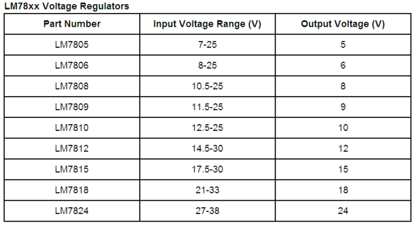
LM78xx Voltage Regulators
There are hundreds of voltage regulators available. The most commonly used are LM78xx series linear regulators manufactured by several companies like Fairchild, Semelab, and ST Microelectronics. They typically come in a TO-220 package, and have a metallic attachment point for a heatsink. The part number designates the output voltage. For example, LM7805 provides a 5 V regulated output, while LM7809 provides a regulated 9 V output. They can provide an output current up to 1 Amp, and have overload and short-circuit protection features.

The figure below shows how to use a LM7805 to get a regulated +5 V power supply. Decoupling capacitors (nominally between 1 uF and 47 uF) are used to filter input and output voltages, and they also help in removing any momentary glitches in the power source. The input DC voltage for LM7805 is obtained by rectifying the low-voltage AC output from a step-down transformer using a diode-bridge rectifier.

Also read: Regulated power supply for breadboard