Author Archives: R-B

ADC channels in PIC16F688

The PIC16F688 microcontroller has a built-in 10-bit ADC with eight input channels. The eight channels are available at RA0, RA1, RA2, RA4, RC0, RC1, RC2, and RC3. They have alternate labels, AN0-AN7, for this function, and are multiplexed into a single sample and Hold circuit. The output of the sample and hold is connected to the input of the A/D converter. The A/D conversion is successive approximation based and the 10-bit result is stored  into the ADC result registers ADRESH (A/D Result Higher byte) and ADRESL (A/D Result Lower byte). Each of these registers is 8-bit.

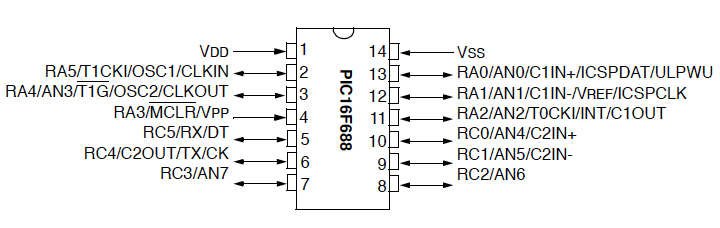
Pin diagram of the PIC16F688 microcontroller

Read more

AVR displays body temperature on a Nokia 3310 LCD

This project describes how to measure temperature with Atmega8 and a thermistor and display it on a Nokia 3310 LCD. A thermistor is a device that changes its resistance with temperature. With a proper resistor divider network, the temperature can be measured by measuring the voltage across the thermistor. The voltage across the thermistor is measured by the on-chip ADC of Atmega8. The necessary coefficients to convert the resistance to temperature are given in the manufacturer’s datasheet of the thermistor. The thermistor used in this project is Vishay NTCLE100E3103JB0 (found at Sparkfun.com).

Read more

Digital I/O Ports in PIC16F688

PIC16F688 is a 14-pin flash-based, 8-bit microcontroller. It can be obtained in different packages, but the DIP (Dual In-line Package) version is recommended for prototyping. The figure below shows a PIC16F688 microcontroller in DIP chip, and its pin outs.

Most of the pins are for input and output, and are arranged as PORTA (6) and PORTC (6), giving a total of 12 I/O pins.  All of these can operate as simple digital I/O pins but they do have more than one function. For example, eight of total 12 I/O pins also serve as analogue inputs for the internal analog-to-digital converter (ADC). Similarly, the PORTA pins RA0 and RA1 are also used to serially load an user program into the PIC16F688 flash memory. The mode of operation of each pin is selected by initializing various control registers inside the chip. All these options will be discussed later on.
Read more

Hardware and Software requirements

The development of an embedded system requires some hardware and software products. Although the hardware requirements depend on the type and complexity of the project, the following hardware tools are required in all of the experiments we are going to discuss here.

  1. A solderless breadboard for constructing and testing the experimental circuits. The breadboard is chosen because it is reusable. You can change, modify or remove the components on it at any time. While an embedded system is in development phase, you never know in advance whether or not your circuit will function correctly when assembled. So it is always good to test it first on a breadboard. Once it performs well, the circuit can be transferred to a printed circuit board.
  2. Microcontroller chips (PIC16F688 and PIC16F628A in this case)
  3. A PIC programmer to load firmware inside the microcontroller. You need to buy one with in circuit serial programming(ICSP) capability. This allows you to quickly program the PIC while it is in the target circuit. I have got an iCP01 USB PIC programmer from iCircuit Technologies. It is very handy, easy to use, and low-cost ICSP programmer for the most popular flash-based PIC microcontrollers. The best thing about it is that it is compatible with Microchip’s PICKit2 and MPLAB IDE softwares. And, it works great. Read Choosing a PIC Programmer.
  4. A PC is required for two purposes: to develop and compile the firmware for the microcontroller, and to transfer it to the PIC programmer so that it could be loaded into the program memory of the microconroller.
  5. A regulated +5V DC source to power your circuit on the breadboard.
  6. A digital multimeter as test equipment.
  7. Other components like resistors, LEDs, capacitors, wires, etc as required.

iCP01 USB PIC programmer that uses PICkit2 software for programming

Required Software Tools

In addition to the above hardware, following software products are required during the experiments.

  1. A Compiler to develop and compile the firmware. You need to download and install the free version of mikroC Pro for PIC (a C compiler for PIC from Mikroelektronika) to follow these experiments. Here is the download link: mikroC Pro for PIC. Also download mikroC Pro manual and Create First Project. These user’s manuals describe the compiler features and setup procedure in detail.
  2. A microcontroller device programmer software that’s provided by the vendor along with the programmer hardware. It is required to transfer the firmware from the PC to the microcontroller. You can download PICkit2 programming software for iCP01 USB PIC programmer here.

Simplest Temperature Data Logger based on PIC12F683

This one chip data logger uses PIC12F683 microcontroller to read temperature from a DS1820 sensor and store it inside its internal EEPROM memory. The process is repeated in every 1 sec, 1 min, or 10 min interval as selected by user. The stored values can be transferred to a host PC through serial port. The serial communication uses a transistor based TTL to RS232 Level converter circuit to transfer data to PC.

This logger can store up to 254 temperature measurements in its internal EEPROM. Each data is 8-bit and the temperature resolution is 1 degree C. With three tact switch inputs, the user can control Start, Stop, Send, Reset, and Sampling time set operations. The hardware and firmware is available for free.

Read more

« Older Entries Recent Entries »