Author Archives: R-B

Open Source USB AVR Programmer for Students and Hobbyists

If you cannot afford to buy a USB programmer for AVR, don’t worry, you can make one by yourself. This programmer uses a Atmega8 microcontroller with a few external passive components. The good thing is you don’t need any USB controller because it is implemented in the firmware inside Atmega8. Yes, you are right, you need an AVR programmer once to load the firmware inside Atmega8. You figure out how you gonna manage that.

This programmer has been tested under Windows, Mac OS X, and Linux and worked well. It can program a chip at speed up to 5Kbytes/sec. The firmware for Atmega8 and necessary drivers for host computer are available for free.

Read more

Regulated Power Supply for Your Breadboard

Embedded systems require electric power to operate. Most of the components in them including the processors can operate at a wide range of voltages. For example, the operating voltage range for PIC16F688 is from 2 to 5.5 V. It means you can supply power from three AA size batteries (4.5 V) and it will work just fine as long as the battery voltage doesn’t fall below 2 V. But there are certain applications where you need a regulated constant voltage for safer operation of the embedded system. For instance, any application that uses analog-to-digital converters (ADCs). ADCs require a fixed reference voltage to provide accurate digital count for input analog signal. If the reference voltage is not stable, the ADC output is meaningless. So, today we are going to make a regulated +5V power source for our lab.

An LM7805 linear regulator IC is used for this purpose. It converts a DC input voltage of range 7-25 V to a stable +5 V. It requires just two external capacitors and is very easy to use, as shown below.

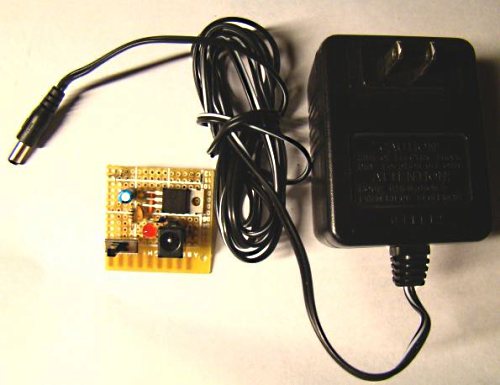
The input DC voltage for LM7805 could be obtained from a 9V DC wall adapter that can supply 1 Amp of load current. Actually, 12 to 24 V adapter will work too, but the LM7805 regulator dissipates an extreme amount of heat energy at higher input voltages and, therefore, requires a bulky heat sink. The wall adapter is chosen because it is cheap, easily available (you might already have got a spare one at home), and safe (the high voltage mains AC is isolated). You can solder this circuit on a general purpose prototyping board. Here are some pictures I took of my power supply unit.

I have soldered male header pins (shown above) to +5 V and Gnd terminals so that the power supply unit can be plugged into the breadboard (shown below).

The power supply unit is ready now. Measure the output voltage with a digital multimeter and see how close is it to +5 V.

Real-time clock and Temperature display on 16×8 LED Matrix

Digital clocks and temperature meters are very popular projects. There are tons of such projects available on internet. This one is little bit different. This displays time and temperature both scrolling on a 16×8 LED matrix.

PIC18F2550 is the brain of this project that controls the columns of the display through A6276 (a 16-bit serial input, constant current latched LED driver). The rows are controlled with a 74ACT164N (8-bit serial-in parallel-out shift register). The required current to drive the rows are provided by BC337 transistors.

A DS1320 serves as the external real time clock, whereas the temperature measurement is performed with LM35, a precision centigrade temperature sensor from National Semiconductors.

Read more

USB Development Board for PIC18F4550

This article shows how to make a low cost USB development board for PIC18F4550 similar to Microchip’s PICDEM USB FS board. The Microchip’s USB stack examples can be compiled and loaded directly without altering the code. Access to each of the 40 pins is provided through female headers so that the connections could be extended to a breadboard easily during prototyping.

The board has got a LM7805 voltage regulator with a polarity protection. This board will be very helpful in prototyping PIC based USB projects.

Read more

50 MHz range frequency counter using AT90S2313

A wide range frequency meter is an useful tool for an electronics lab. This projects describes a frequency meter based on AT90S231 microcontroller that can measure input frequencies up to 50 MHz. The measured frequency is displayed on 6 digit multiplexed seven segment displays.

It uses two external high-speed 8-bit counters (74HC590) in cascade to count the incoming pulses. Depending upon the input frequency, the counting interval for the external counter circuit is changed by the microcontroller for getting better accuracy. The firmware for AT90S231 is provided in C.
Read more

« Older Entries Recent Entries »