Starling: A wifi enabled LED matrix display
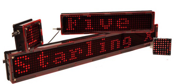
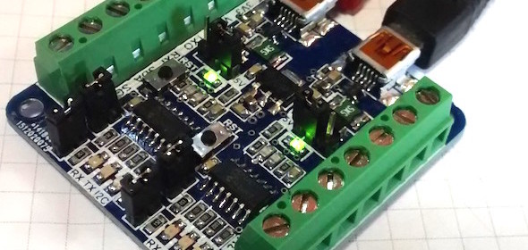
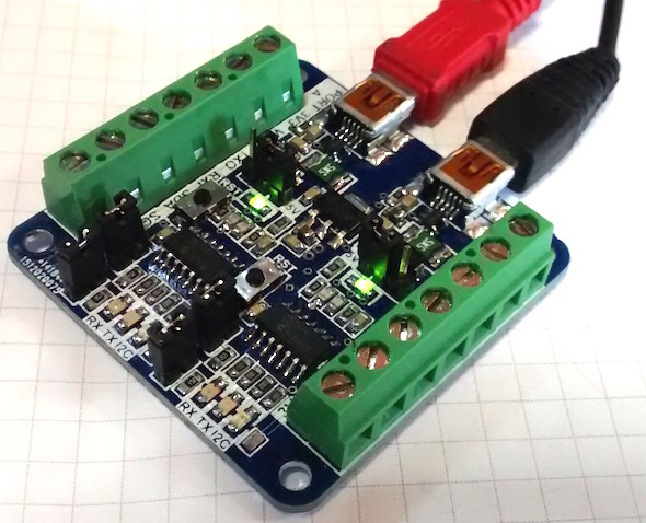
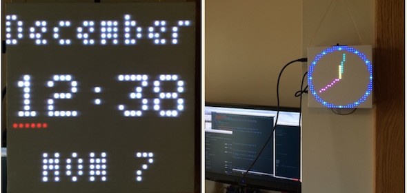
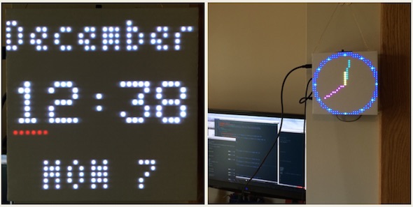
Explore Embedded, a Banglore, India based startup has introduced a modular and wifi enabled LED matrix display named Starling, that can not only showcase text messages but also notifications from social networking websites, live scores from sports events websites, weather data from online weather services, and more. Starling comes in an easily cascadable modular design with one master module that features the ESP8266 device for Wifi connection and other slave modules to expand the display size horizontally. Each module is powered by Atmega8 microcontroller that stores fonts and custom characters LED patterns in a look up table, drives its own 8×8 LED matrix, and also communicates with other modules along the chain. In fact, the master module is smart enough to recognize the number of slave modules connected along the row and to receive the display data from anywhere using mobile and web apps. For those of you who would like to grab one of these displays in hands at discounted price, you may want to support their crowd-funding campaign. This project is only seeking $5000 on Crowd Supply. Also check out my portable bluetooth-enabled LED matrix display project that I build a while ago.
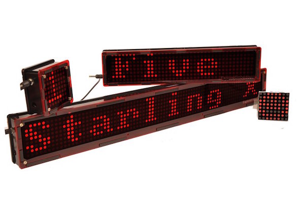
Starling: A Wifi enabled LED matrix display