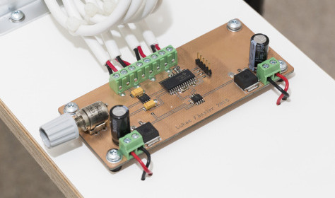
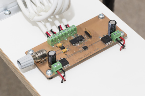
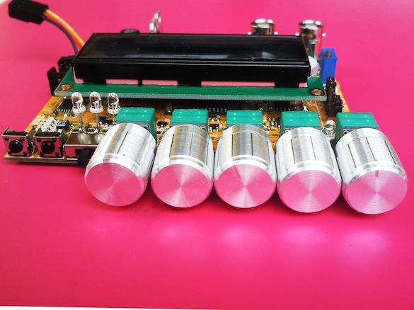
MAX038 function generator
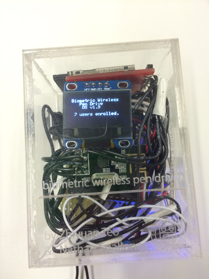
Milen posted this Instructable on the design of a MAX038 function generator that also implements an Atmega328 and an LCD to display the parameters.
Max038 function generator
The function generator is very useful tool for the electronics freaks. It is needed for tuning resonance circuits, testing audio and video equipment, designing of analog filters and for many other different purposes.
Today there are two main types of function generators ; digital, (DSP based, DDS…) which are more and more often used and analog, which were the origins.
Both types have their advantages and disadvantages. The digital generators can generate signals with very stable frequency, but they have problems with generating very pure sine signals (what is not problem for analog one). Also the mainly spread function generators based on DDS approach have not so big frequency generation range.
Since long time I wanted to design a useful function generator, which could somehow combine some of the advantages of both types (analog and digital) generators. I decided to base the design on the Maxim chip MAX038*