Microchip is launching “Curiosity” development board
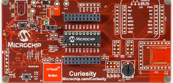
Microchip is launching a new development board called Curiosity for 8-bit PIC lovers. It supports 8-, 14-, 20-pin 8-bit PIC® Microcontrollers with low voltage programming capability and has an integrated Programmer/Debugger with USB Interface that is fully compatible with Microchip’s MPLAB X development environment.

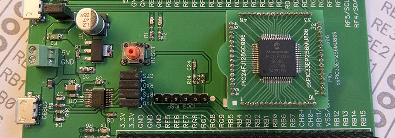
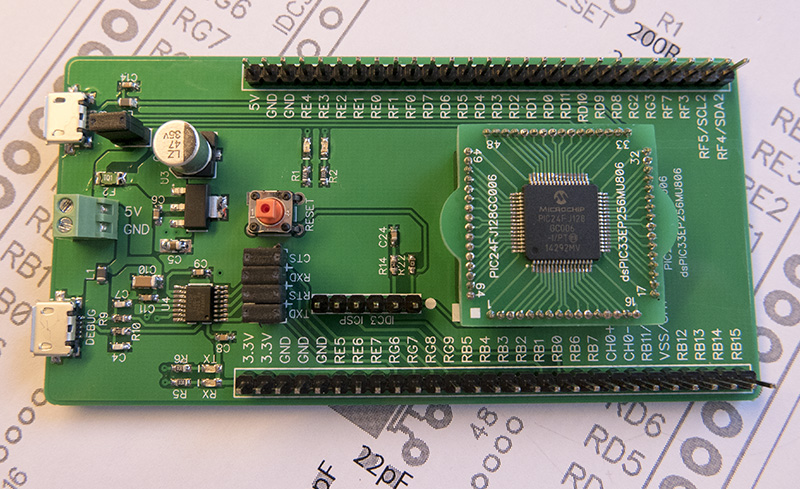
Curiosity development board from Microchip
Your next embedded design idea has a new home. Curiosity is a cost-effective, fully integrated 8-bit development platform targeted at first-time users, Makers, and those seeking a feature-rich rapid prototyping board. Designed from the ground-up to take full advantage of Microchip’s MPLAB X development environment, Curiosity includes an integrated programmer/debugger, and requires no additional hardware to get started.
Curiosity is the perfect platform to harness the power of modern 8-bit PIC® Microcontrollers. Its layout and external connections offer unparalleled access to the Core Independent Peripherals (CIPs) available on many newer 8-bit PIC MCUs. These CIPs enable the user to integrate various system functions onto a single MCU, simplifying the design and keeping system power consumption and BOM cost low.
Also, check out Mike Szczys‘ (over Hackaday) reviews of this new PIC development board here.