Author Archives: R-B

Embedded Lab wishes you a very happy new year

Christmas is over and we are now geared up to say good bye to 2014 and welcome to 2015. Embedded Lab would like to wish all of our readers, supporters, and contributors a very happy and prosperous new year. May 2015 bring you all the great things in your life.

And here is the last discount coupon for this year. The discount offer starts now and will run until Jan 1st, 2015.

15% OFF using the code: 6BCF43D

Applicable to all serial seven segment LED displays, Easy Pulse sensor, and cascadable LED matrix displays.

If you are not familiar with latest Easy Matrix displays, check out this cool Bluetooth controlled scrolling LED matrix display project using these modules.

Easy Matrix display

Scrolling Easy Matrix display with Bluetooth control

Thanks a lot for your support!

Selfiebot: An autonomous photo capturing system

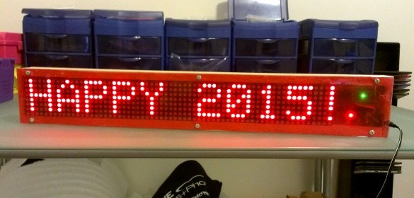
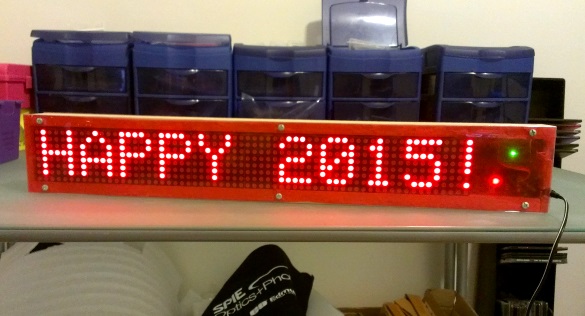
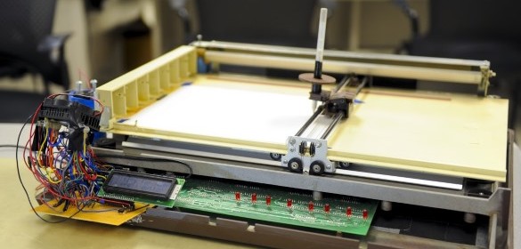
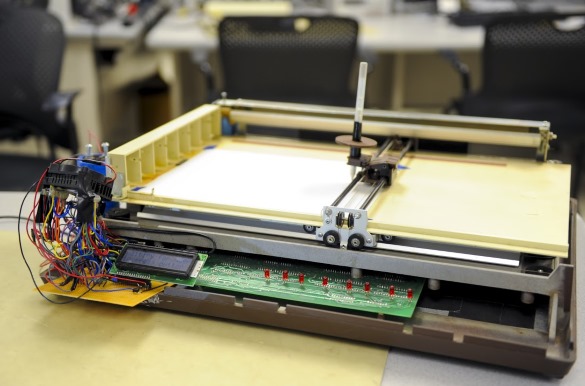
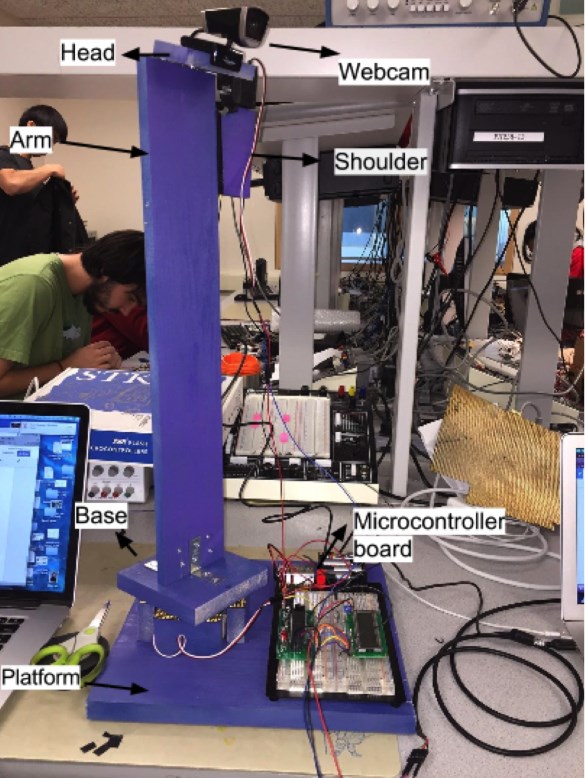
Two Cornell University students, Michael Wang and Jennifer Qian, have built Selfiebot, a personal photo companion that will capture your special moments autonomously. It consists of a physical selfie robot unit with camera holder (webcam in this example) that can pan and tilt the camera for proper positioning, and a control module residing in a laptop computer that relays pan and tilt commands to the robot based on the feedback received from the camera. The user gets control of various settings such as image properties, centering properties, and photo taking parameters.

Michael and Jennifer write,

We have designed and constructed an autonomous photo capturing system that detects and tracks faces, centers subjects in the frame, and takes pictures. Since the most straightforward application for our robot is to take pictures of oneself without the aid of others, we have fittingly dubbed our system the “Selfiebot”. When operating our device, the user may specify a variety of preferences through its simple GUI, including contrast, brightness, centering options, the number of people to capture, and the number of pictures to take.

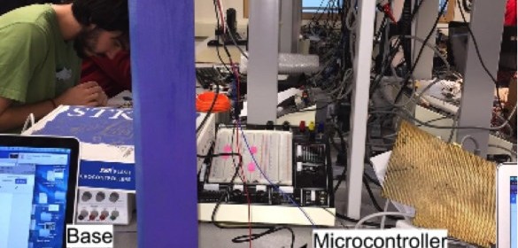
Our system processes images taken from a webcam on a laptop computer, using facial detection to track subjects, and forms movement commands to center the subjects based on face positions. The laptop sends the commands to an ATmega1284 microcontroller via serial communication, and the microcontroller controls the movement of two servos on the robot. These two servos correspond with panning and tilting actions, allowing for two dimensional movement of the camera. Feedback from the camera is used to continuously update movement.

Selfiebot personal photo companion

Selfiebot personal photo companion

Check out there demo video below.

Breadboard adapter for ESP8266 module

ESP8266 is an inexpensive serial-to-wifi tranceiver chip that allows to connect any microcontroller with a serial port to a WiFi network. Because of its simplicity and low cost, it is getting popular among hobbyists for building Internet of Things (IoT) applications. While there are varieties of breakout boards available for ESP8266 from the Chinese markets, the most popular one is the ESP-01 version that provides access to the ESP8266 pins through a 2×4 male header. While the headers are 0.1″ pitch, the pin arrangements are not breadboard friendly and are not labeled on board, which makes it little inconvenient for breadboarding. I have designed a very simple breadboard friendly adapter (shown below) with clear pin labels printed on the board to make prototyping with the ESP-01 module easier.

ESP8266 breadboard adapter

ESP8266 breadboard adapter

Buy Adapter only from Elecrow Store (recommended for international buyers)
Buy Adapter plus ESP-01 module from Elecrow Store (recommended for international buyers)

The adapter has a 2×4 female header to receive the ESP-01 module and a 10uF power supply filter on board. The ESP-01 module pins are accessible through two single row headers that are breadboard friendly. The Eagle design files are provided at the end of the page.

You can buy ESP-01 module and kit together from our Elecrow Store

ESP82663

ESP-01 module plugged into the breadboard adapter

If you are interested, you can get this adapter from our Tindie Store.

ESP82662

ESP8266 adapter kit

ESP8266 Adapter Design Files

Buy ESP8266 breadboard adapter kit

Circuit printer: A rapid prototyping machine for electrical circuits

Another interesting micrcontroller-based design project done by Bruce Land‘s students at Cornell this fall is a circuit printer, a rapid prototyping machine that prints electrical circuits on a piece of paper. Designed by Connor Archard and Feiran Chen, this printer uses an electrically conductive ink pen to rapidly create circuits. The circuit to be printed is drawn through an Web-app and can be sent to the printer from anywhere in the local area network.

Circuit printer machine

Circuit printer machine

As shown in the following demo video, the Web-app allows users to draw out circuits quickly, converts them into vectors and then send them out frame by frame over a WiFi network to the server, which in turn communicates with an Atmega1284P microcontroller embedded into the printer. The Atmega1284P then controls the x and y-axis motors, and raises and lowers the pen as instructed to print the circuit. By measuring the position of the plotter head on each axis through the on-chip ADC and two servo potentiometers, the Atmega1284P processor is able to control the plotter head with an accuracy of approximately 1/10th of an inch on a typical piece of A4 paper.

Connor and Feiran have the following vision about their project,
This idea is aimed to make mass prototyping circuits on flexible surfaces so cheap and easy, and we see a great potential for this product both in industry and remote education. For future improvement, we are thinking of supporting multi-layer, multi-dimension circuits, and designing our own mechanics and support frame for the machine.

Single digit Nixie clock driven by PIC16F84A

This IN-18 Nixie tube clock project  utilizes the PIC16F84A microcontroller and displays hours and minutes on a single tube. The circuitry is simple and the author used salvaged parts from a disposable camera to construct the high voltage power supply required for the Nixie tube. The time is displayed in the single digit by periodically flashing the digits from tens of hours to minutes. A tact switch is also implemented to set the time. It has to be pushed when the digit you want to change is being displayed. The current display is increased by one each time the switch is pressed and cycle through 0-9.

Single digit nixie clock

Single digit nixie clock

« Older Entries Recent Entries »