With the rapid development and maturing of internet-of-things (IoT) technology, the IoT-driven smart sensors and systems are changing business in multiple industries. In healthcare industry, it is gaining more attention lately because of its immense potential in reducing the cost of tracking health information, as well as in providing health care to people who were not able to receive it before. This project describes a simple remote heart rate monitoring system based on the ESP8266 platform and the Easy Pulse Plugin sensor module. The ESP8266 reads in the analog photoplethysmograph (PPG) output from the Easy Pulse sensor, computes the heart beat rate in real time, and post it to a Google spreadsheet for remote access. A TFT LCD is also installed to display the PPG waveform and pulse rate locally.
IoT enabled pulse meter
Hardware
For just the IoT capability of this project, you only need an ESP8266 module and the Easy Pulse Plugin sensor. If you like to display the PPG waveform and pulse rate locally, you will also need an ILI9341-based TFT LCD. You would also need to read my Tutorial 7 on how to use an ILI9341 TFT display with ESP8266. For illustration of this project, I am using EasyESP-1 board. But you can do this with NodeMCU or any other ESP8266 breakout board that has adequate GPIOs to drive the TFT and access to the ESP8266 analog input.
Hardware required:
Easy Pulse sensor setup
Easy Pulse Plugin operates on the principle of Photoplethysmography, which is an optical technique of sensing blood volume changes in tissues by illuminating the skin surface with a light source and measuring the reflected or transmitted light using a photodetector. The photodetector output contains the cardiovascular pulse wave, which is synchronized with the beating of the heart. Easy Pulse Plugin provides all necessary instrumentation and amplification on board to detect the cardiovascular pulse signal from the fingertip. The most important characteristics of Easy Pulse Plugin is that it can be easily plugged into the left headers of Arduino Uno (or its compatible clone) board for easy interfacing, and the analog pulse signal can be fed to either A0 or A1 analog input through a 2-pin jumper selection. It can also be plugged into a breadboard for prototyping with other microcontroller platforms. You can buy this sensor at our Tindie Store as well as from Elecrow with worldwide shipping.
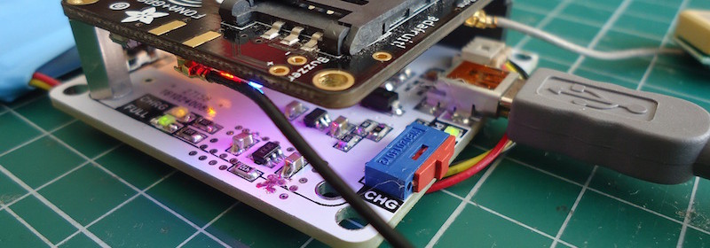
For this project, the jumper settings of Easy Pulse module are as follows (also see the following picture).
- JP1 is set to 3.3V, which means the analog PPG output swing range is 3.3V max.
- JP2 is set to A0, which means the analog PPG signal is available at A0 pin.
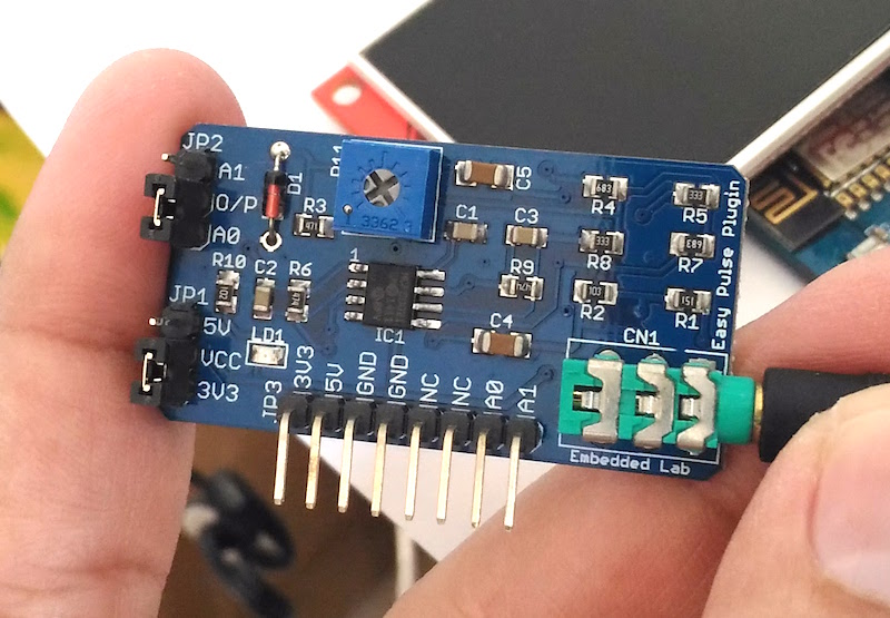
JP1 and JP2 shunt jumper settings for this project. The PPG signal is available at A0 header pin.
The Easy Pulse Plugin module is plugged into the breadboard area of EasyESP-1 board. The 3.3V, GND, and A0 pins are connected to the 3.3V, GND, and AN header pins of EasyESP-1 board, respectively. The TFT LCD connections are same as described in Tutorial 7, and are also shown below.
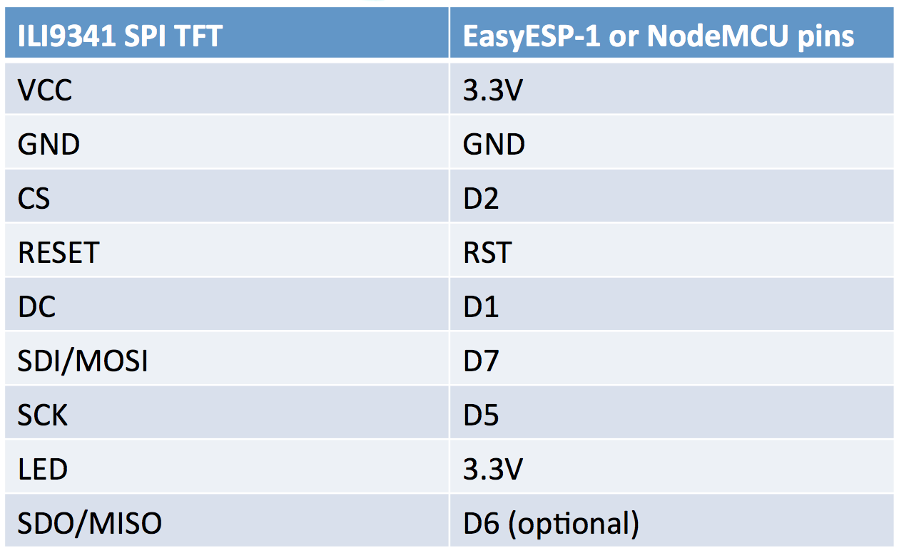
Connections between ILI9341 SPI TFT module and EasyESP-1
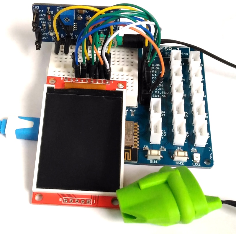
Complete project hardware setup
Software
There are two parts of the software for this project. The first part involves writing the firmware for ESP8266 using Arduino IDE. This part covers analyzing the Easy Pulse sensor output, processing the PPG signal to compute the heart beat rate, displaying it on the local TFT display, and connecting to a Google script to post the heart beat rate to a spreadsheet over the internet. Posting the data to a Google spreadsheet follows the same technique as described by Anir in this tutorial. The second part of the software development involves writing the Google script that will receive the heart beat rate from ESP8266 and post it on a Google spreadsheet.
The ESP8266 software written in Arduino IDE can be downloaded from the following link.
Download ESP8266 Arduino Code
You need to install the following Arduino libraries prior to compile the above code.
TFT ILI9341 ESP library
HTTPSRedirect library from Sujay Phadke
Read HOW TO POST DATA TO GOOGLE SHEETS USING ESP8266 for more details on HTTPSRedirect library.
The ESP8266 digitizes the analog PPG signal using the ADC input channel. The sampling rate is 5 milliseconds. It acquires 600 samples at a time (in 3 seconds) and computes the instantaneous heart beat or pulse rate by detecting three consecutive peaks in the PPG waveform. The details of this algorithm of computing the heart beat rate is described in my previous project. The PPG waveform and so computed pulse rate are displayed on the TFT LCD. In order for the ESP8266 to post the data to Google sheet, you need to make the following changes to the ESP8266 program.
- Update the ssid and password in the code to match to your WiFi network.
- Also, you will also need to update the *GScriptId, which can only be obtained after publishing the required Google App Scripts, which is discussed below. So, you can’t upload this code to your ESP8266 until you have your GScriptId ready.
const char* ssid = "Your SSID";
const char* password = "Your Password";
const char *GScriptId = "Your GScriptid";
Google scripts
Next step is to prepare a spread sheet in your Google drive and create a Google App script to access it via URL. First, create a Google spreadsheet in your Google Drive and name it something, say IoTPulseDemo. Rename the current/active sheet to DataLogger. From the URL address bar of the sheet, copy the string between d/ and /edit and save it somewhere. This is your spreadsheet’s unique sharing key, which will be needed in the Google Apps scripts later. In the DataLogger sheet, type ID, Time, and Value in A1, B1, and C1 cells, respectively. See the screenshot posted below.
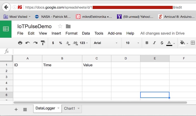
Preparing the spreadsheet
Next, to create a Google App Scripts, go to Tools > Script Editor from the Google Sheets. The Script Editor opens in a new tab. Then copy the Google App Script code from the following .txt file and paste it there. The code or script can be saved under any name.
Download Google App Script
It is important that the sheet name in the script should match to that you want to be populated.
var dataLoggerSheet = ss.getSheetByName("DataLogger");
|
Similarly, you would also need to edit the spreadsheet sharing key in the script to match with yours (one you copied from the spreadsheet URL earlier).
var ss = SpreadsheetApp.openByUrl("https://docs.google.com/spreadsheets/d/---Your-Google-Sheet-ID--Goes-Here---/edit");
|
Deploy the contents as Web app
Next step is to publish the script so that it is accessible through an URL. In order to do that, select Publish > Deploy as Web App from your gscript editor window. Make sure you allow the access to the app to “Anyone, even anonymous“, as shown below.
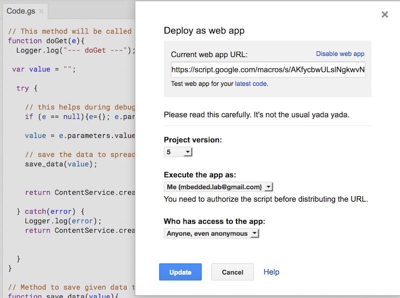
Deploying the script as Web App
Note: Whenever you modify your code, you have to create a “New” Project version and publish it otherwise you will still be hitting the same old code.
Copy the Current web app URL and save it somewhere as we will need it for extracting the GScriptID. The web app URL would look like this:
https://script.google.com/macros/s/AKfycbwULslNgkwvNQfKcsXJPVygL9uO/exec
The string between s/ and /exec is your GScriptID. Copy this GScriptID and paste it to your ESP8266 Arduino code,
const char *GScriptId = "paste here";
Now your ESP8266 code is complete and can be uploaded to the ESP8266 module.
During script publishing, Google will ask to grant some of the permissions and you need to allow those.
Output
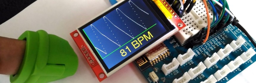
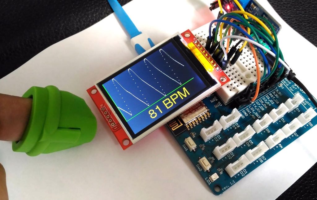
After uploading the firmware to ESP8266 and publishing the Web App, the heart rate monitoring project is ready to run. Wear the pulse sensor on the tip of your index finger and power the EasyESP-1 board. In the beginning, the ESP8266 runs the setup program that performs TFT LCD initializing and connecting to your WiFi network. You can open a serial monitor window on the Arduino IDE to check the progress. After the setup is complete, you will see a PPG waveform derived from 600 analog samples displayed on the TFT screen. The pulse rate in BPM is also shown. The ESP8266 accesses the Google App script via URL using the GScriptID to send the pulse rate. The Google script then posts the pulse rate and time stamp to DataLogger spreadsheet. If you open the spreadsheet on your Google drive, you will see it populated continuously as the ESP8266 sends the data.
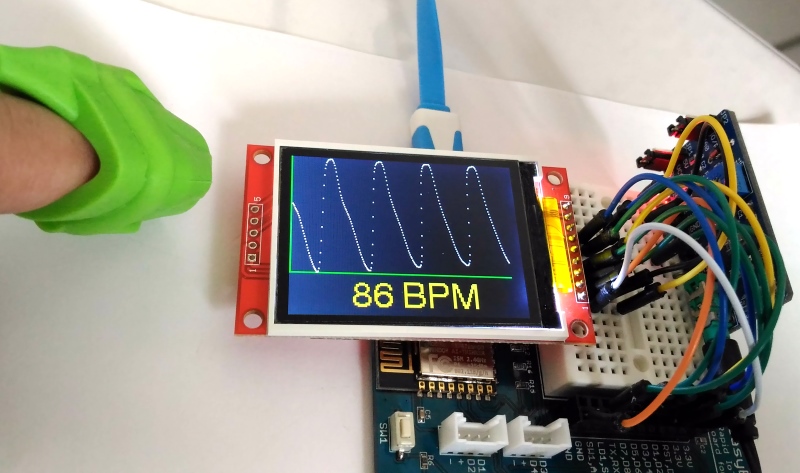
Local display of PPG waveform and pulse rate
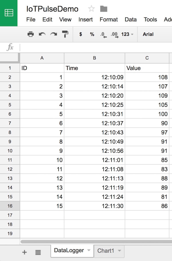
DataLogger sheet populates with pulse rate data and time stamp
You can also use Google sheet chart feature to visualize the pulse rate variation over time.
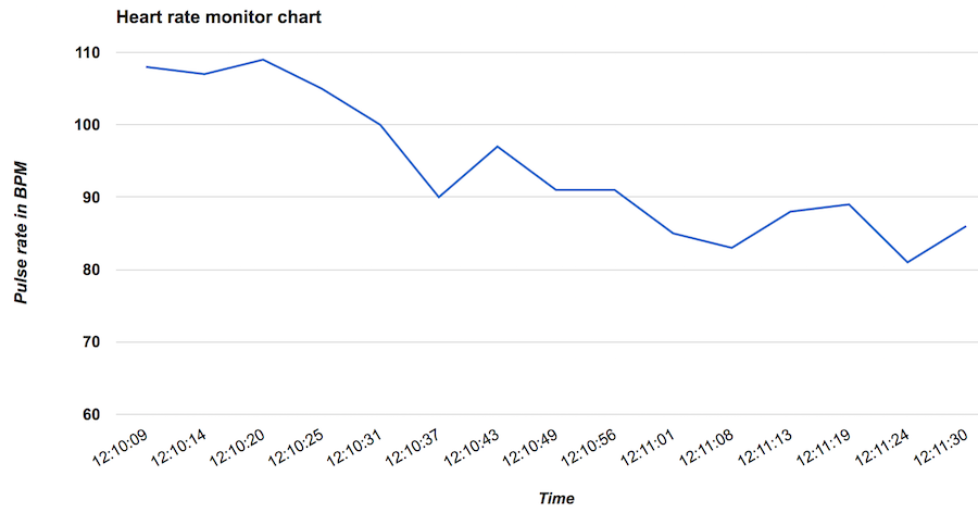
Pulse rate tracking over time