BME280 is a fully integrated environmental unit from Bosch that combines sensors for pressure, humidity, and temperature in a tiny 8-pin metal-lid LGA package of size 2.5 x 2.5 x 0.93 mm³. Because of its compact size, ease of use (BME280 supports standard I2C and SPI interfaces), and availability of supporting open-source Arduino libraries, BME280 is very popular among weather enthusiasts. This project describes how to read barometric pressure, relative humidity, and temperature measurements from BME280 using chipKIT Uno32 to make a standalone weather station. The sensor readings are acquired over an I2C bus and are displayed on a Nokia 5110 LCD display.
BME280 weather station
Hardware setup
Nokia 5110 LCD was used in Nokia’s popular 5110 and 3310 model cell phones. It is a 48×84 pixels matrix LCD driven by the low-power PCD8544 controller chip. It is powered by 3.3V and includes on-chip generation of LCD supply and bias voltages, thus requiring minimum external components for its operation. The PCD8544 receives display data and commands from a microcontroller through a serial bus interface.
The LCD requires 5 I/O pins for full control. The pins available in almost every Nokia 5110 LCD modules are listed below:
- RST: Display reset input
- CE: Chip enable input
- DC: Data or Command select signal
- DIN: Serial data input
- CLK: Clock input
- VCC: 3.3V power supply
- BL: Backlight LED anode (connect to 3.3V)
- GND: Power supply ground
The connections between the chipKIT Uno32 and Nokia 5110 LCD are similar to what I used before in this article. The following figure shows the pin connections between the two.
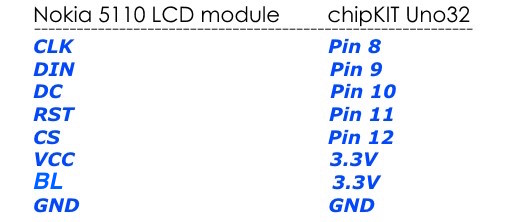
Pin connections between Nokia 5110 LCD and chipKIT Uno32
There are lots of BME280 breakout modules available in the market. You can use any of them with access to the I2C pins. The SDA and SCL pins are then connected to A4 and A5 pins of chipKIT Uno32, respectively. Note that in order to use the A4 and A5 pins for I2C operation, the JP6 and JP8 jumpers on board chipKIT Uno32 must be placed in RG3 and RG2 positions, respectively. They are placed in the RG3/RG2 position to use the pins for I2C operation. The complete hardware setup for this project is shown in the following figure.
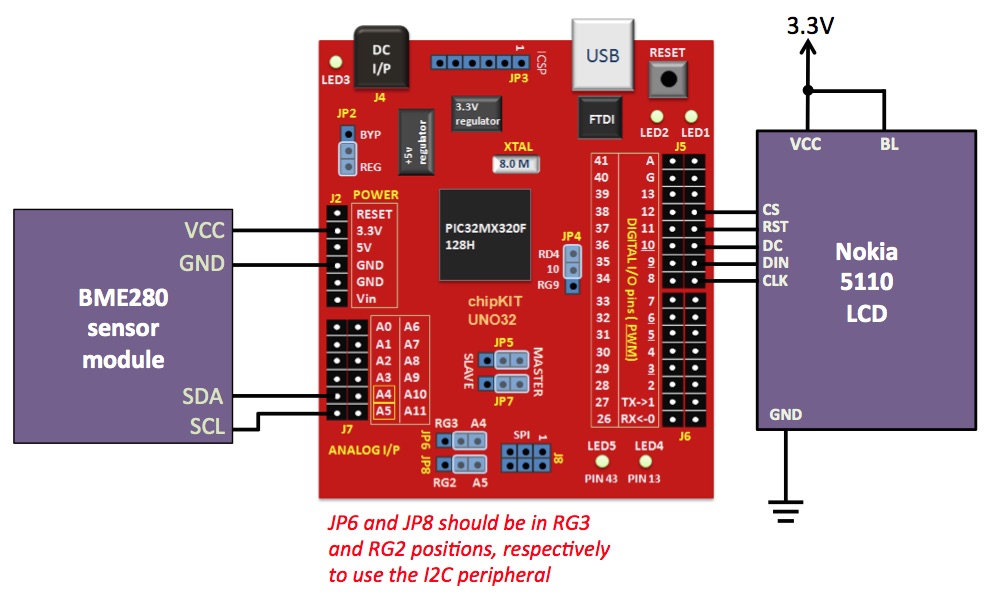
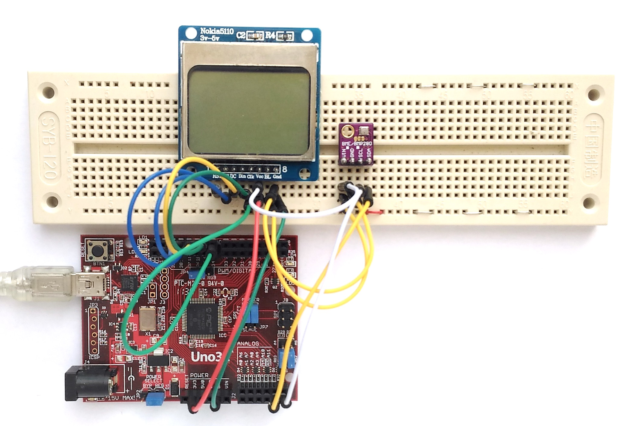
Connections between chipKIT Uno32, BME280 and Nokia 5110 LCD

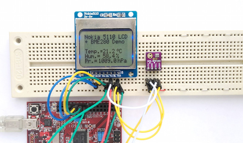
The actual setup of the project. The Nokia5110 LCD and BME280 sensor modules are laid out on a breadboard.
Software
We will need to install the following libraries prior to develop the firmware for this project.
Adafruit unified sensor library
Adafruit BME280 library
Nokia 5110 LCD library for chipKIT from Rinky-Dink Electronics, which contains two versions of the LCD libraries: LCD5110_Basic, which supports texts, and LCD5110_Graph, which supports text, graph, and bitmaps. In this project, only the Basic library is used, which can be downloaded from the following link.
Download LCD5110_Basic
The complete chipKIT program for this project can be downloaded from the following link:
Download_BME280_Weather_Station_Firmware
The program displays ambient temperature in Centigrade, humidity in %, and atmospheric pressure in hectopascal (hPa) units.
Output
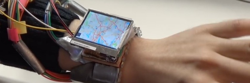
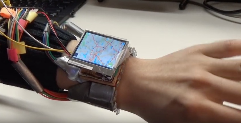
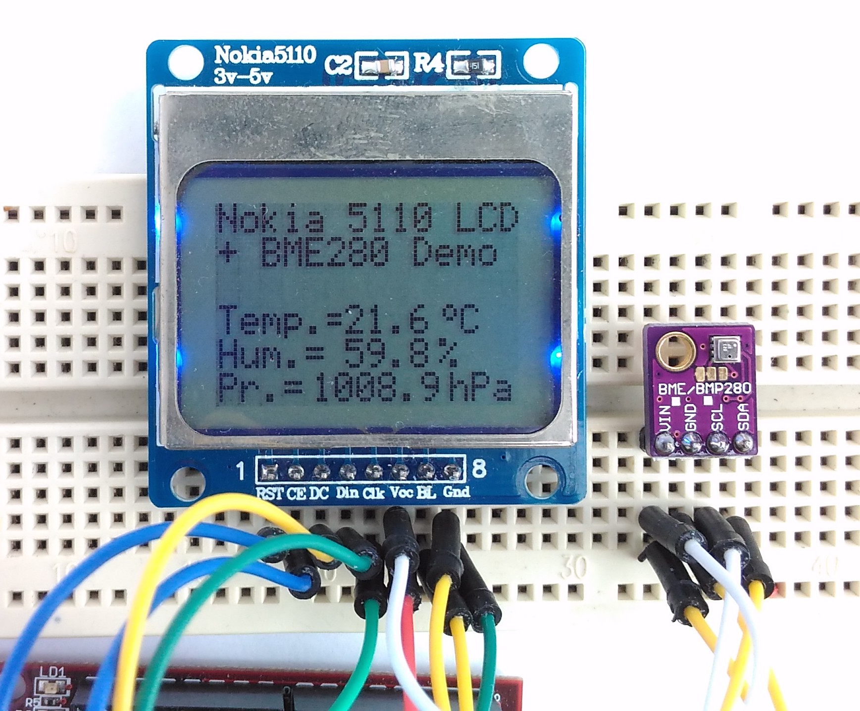
After uploading the program to Uno32 board, the weather station is ready to rock. The following pictures shows the output displayed on the LCD screen.
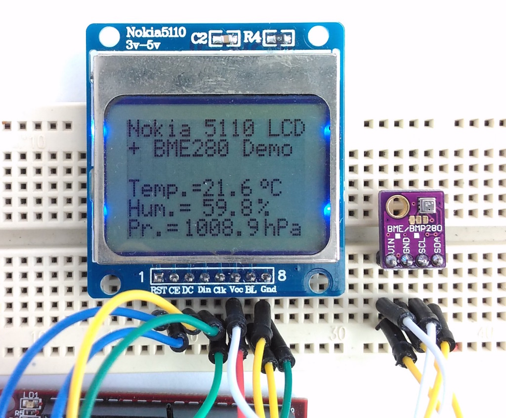
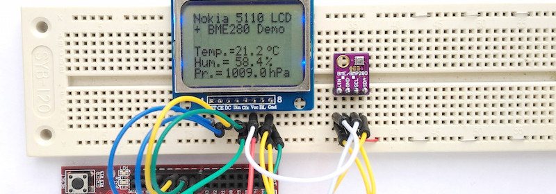
Weather station displaying temperature, humidity, and pressure.
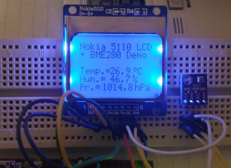
Atmospheric pressure is shown in hPa unit.