BuzzWatch: A personal tactile reminder
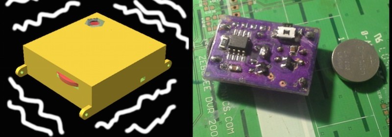
BuzzWatch is a wearable tactile reminder device that can be programmed to vibrate at constant or random intervals notifying the wearer about the passage of time, as well as prompting them to think about what they are doing, and if they need to be somewhere else at the moment. The device uses the Atmel ATTiny13A MCU as its brain, with a thumbwheel potentiometer for setting the time interval of the reminder. A tiny vibrating motor works as a buzzer in the device. The whole electronics fit into a 3D printed ABS case with dimensions of 30x30x9mm. BuzzWatch runs off a 1225 lithium coin cell. In order to prolong the battery life, the ATTiny13A remains mostly in sleep mode. If you sit in front of the computer for hours, this device can serve as an alert telling you when it’s time to get up from your seat and stretch.
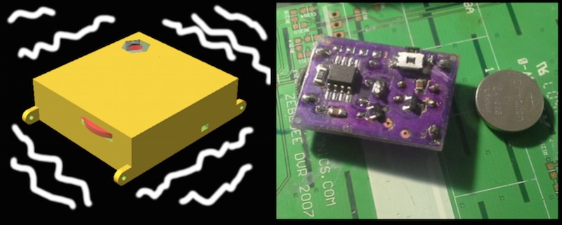
Personal tactile reminder
I used SMD components to keep the device thickness (and also the amount of holes to drill) to a minimum. The only two through-hole parts are the pot and the battery clip. These two also define the dimensions of the board, it could’ve been somewhat smaller otherwise. It’s a one-sided design, which makes it more convenient for home etching. I used photoresistive film as both etching mask and solder mask and a CuSO₄-based etchant. The μC footprint can accomodate both the -SU and -SSU versions of the ‘tiny13. Due to the small size of the board, including a standard ICSP header would be impractical, so contact pads with standard 2.54mm spacing (matching the t13-P pinout so that the jig could later be used in breadboards) are provided instead. Ideally the jig/adapter would use pogo pins, but since I don’t have those I used sewing needles instead and soldered it to the board for the duration of the development.