A buck-boost (also known as step-down and step-up) converter is a type of DC-to-DC converter that combines the principles of the buck and boost switched mode power supplies in a single circuit. What this means is the input voltage could be either higher or lower than the desired output voltage. The Buck-boost converter is very useful in battery-powered systems, where the battery voltage can vary quite a bit depending upon its charge condition and usage, to derive a stable DC supply for an electronics circuit.
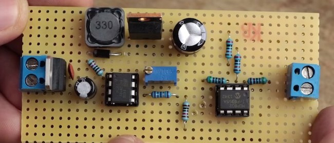
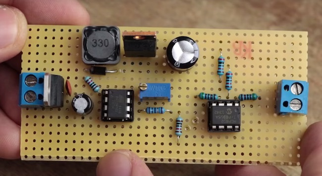
DIY buck-boost converter
GreatScott‘s new Youtube video tutorial explains the basics of Buck-Boost converters and shows how to build a 12V Buck-Boost converter using discrete components like MOSFETs, inductors, and Opamp. The square wave of varying duty cycle, which is a key component of any buck and boost converter, is generated by the ATtiny85 MCU. The output of this buck-boost converter is inverted, and therefore, an Opamp circuit is required to correct the polarity of the output for the feedback signal that goes back to the MCU. Based on the magnitude of the feedback voltage, the ATtiny85 controls the duty cycle of the square wave to stabilize the output voltage.
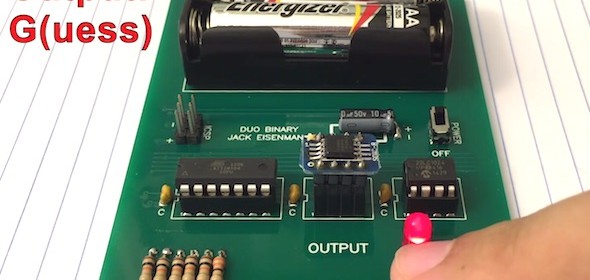
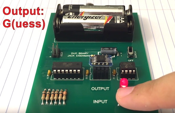
Designed by Jack Eisenmann, the DUO Binary is an ATTiny84-based computer with a single button for input and a single LED for output.
DUO Binary computer
Video demonstration of DUO Binary is posted below.
Parts used:
Microcontroller: ATTINY84-20PU
(x2) 3 pin male header: 69190-403
2 MB flash: SST25VF016B-50-4C-S2AF
128 KB SRAM: 23LC1024-I/P
14 pin IC socket: 4814-3000-CP
8 pin IC socket: 4808-3000-CP
(x2) 4 pin female header: 929974-01-04-RK
(x2) 4 pin male header: 68000-104HLF
SOIC to DIP board: 485-1212
(x3) 0.1 uF capacitor: K104K15X7RF5TL2
Button: B3F-1000
LED: WP7113GD
300 ohm resistor: 291-330-RC
(x5) 10K ohm resistor: 291-10K-RC
(x1 for microcontroller reset, x1 for MISO, x1 for flash CE, x1 for SRAM CE, x1 for button)
Larger capacitor: UVR1H100MDD1TA
Switch: MHSS1104
Battery holder: 534-2462
“User interface”:
The user and computer take turns transmitting 6-bit character encoded strings to each other. Strings are terminated by the null character. Characters are transmitted from most significant to least significant bit. After each character the listener will transmit an acknowledge bit. If the acknowledge bit is 1, the transmitter should send the same byte again. A 0 is represented by a short pulse. A 1 is represented by a long pulse.
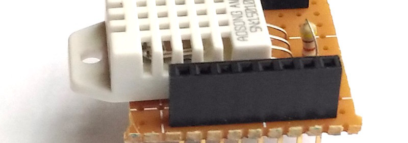
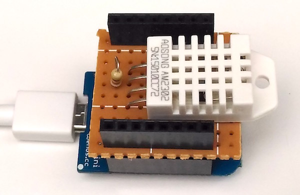
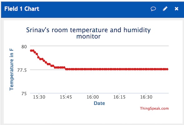
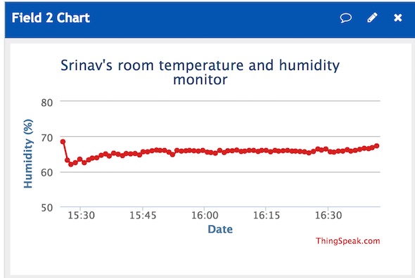
ESP8266 has made it possible for hobbyists and makers to develop IoT applications in simple and inexpensive ways. This article shows an example of making a very simple temperature and humidity logger using ESP8266 that uploads the data directly to a cloud service, such as ThingSpeak, and allows to visualize the data in real time. The ESP8266 module used in this project is WeMOS’ D1 Mini board. Because the D1 board comes with the CH340G USB to UART converter module and a micro USB connector preinstalled on board, all you need is an USB cable to upload your program to the ESP8266. For temperature and humidity measurements, the DHT22 sensor is used. The sensor circuit is soldered on a prototyping circuit board in the form of a shield that plugs directly into the D1 Mini board. Unlike many other similar projects on the internet, this article talks about how to put the ESP8266 into deep sleep mode and configure it to wake up automatically at regular intervals for sensor readings.
IoT temperature/humidity logger using WeMOS D1 Mini board and DHT22 sensor
Circuit setup
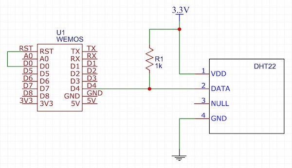
The connection between the DHT22 and D1 Mini board is shown in the figure below. The DHT22 sensor is powered by the 3.3V power supply coming from the D1 Mini board. A 2.2K resistor pulls the DHT22 data pin to high at default. The DHT22 data pin goes to the D4 pin of WeMOS D1 Mini.
DHT22 and WeMOS D1 Mini connections
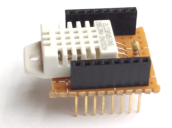
As I mentioned earlier, this project implements deep sleep mode of ESP8266 to save power as well as to get accurate temperature readings. ESP8266 is power hungry and dissipates considerable amount of heat during operation. I have noticed that if the ESP8266 is not put in to sleep during successive sensor readings, the heat radiated by the ESP8266 can easily affects the DHT22 outputs if the sensor is close to the ESP module. In this project, the DHT22 sensor lies on the top shield right above the ESP8266 chip, so it is very important to consider using the deep sleep mode feature. Without using this feature, I have found the temperature readings from DHT22 are 2-3 ºF higher than the actual values. ESP8266 can be put into deep sleep mode with a software instruction. But, in order for it to automatically wake up from sleep mode after a certain interval, the XPD (D0 in D1 Mini board) pin must be tied to the ESP8266’s reset line as shown in the circuit diagram above. The DHT22 circuit is built on a perf board in the form of a D1 Mini shield as shown below.
DHT22 sensor shield
Software
The ESP8266 program for this project is developed using Arduino IDE. So, you need to install the ESP8266 core to enable the Arduino IDE for ESP8266 programming. Instructions can be found in the ESP8266 core github page. Similarly, you would also need to sign up for a ThingSpeak account and obtain a Write API Key, which is required to upload data to ThingSpeak. You can find instructions to do that online. The following Youtube video link is one example.
The complete ESP8266 code for this project can be downloaded from the following link:
Make sure you update the SSID, Wifi password, and ThingSpeak API to match with yours. The temperature and humidity readings are acquired from DHT22 in every 60 seconds and are uploaded to ThingSpeak server. Between two samples, the ESP8266 is put to sleep using ESP.deepSleep() function in Arduino IDE.
If everything worked fine, you would see the temperature and humidity measurements profiles on your ThingSpeak channel graphs.
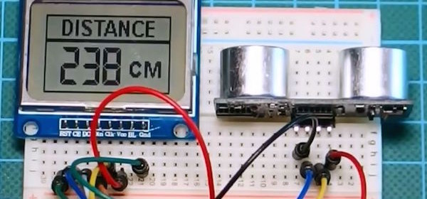
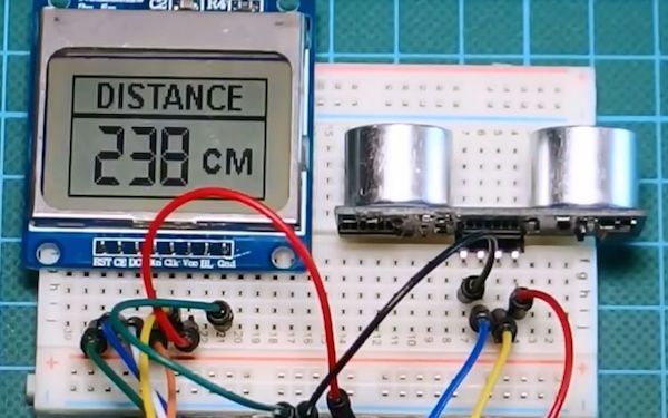
HC-SR04 is a very popular ultrasonic sensor for short distance measurements in DIY projects. This Instructable describes how to use it with an Arduino board to build an inexpensive distance meter with range 2-400cm. The measured distance is displayed on a Nokia 5110 LCD screen using a large size font for improved readability. The Instructable explains the details of how the HC-SR04 sensor works and can be interfaced with the Arduino for ranging with an accuracy of 3mm.
Arduino distance meter
In simpler words, the sensor, sends an ultrasound, then it detects wheather this ultrasound has bounced off of an object or not. If the ultrasound has bounced off, it measures the time that it took it to bounce. Since we know the speed of sound, we can easily measure the distance that the ultrasound traveled!
The following video tutorial from the author explains all these details:
Eric Dirgahayu’s robotic fish is made of PVC pipe and waterproof servos that are controlled by an Arduino board. Her future plans are to include sensors to measure the quality of water and a few other devices to study underwater ecosystems without disturbing the marine life. It is controlled by an IR remote.
Arduino powered robotic fish
First we prepare materials that we will use to create the head of robot fish. the material is a flatten water pipe pvc how to Flatten the water pipe you can see on my previous Intructables here
If you already get flatted pvc, you can download PDF patterns design head of Robot Fish at this step or at my website print image pattern be sure the size is correct , cut and paste the pattern print on pvc flatt and cut the pvc plate fits a pattern, Paste the pattern on each side of the pattern like in the picture, for buckling pvc use blowers to heat the pvc later buckling. it is the same way you make a papercarft but it using a pvc flat. to connect each section use super strong glue (nb : be carefull using a super glue). For the gill cover using a small hinge so that it could move to open the lid. make a hole on the lip and head of robot Fish like the last picture. join the part using a screw. last making a hoe for screw on the top dan bottom the head like the picture that screw hole for join the head to the body.