Author Archives: R-B

Solar powered USB power bank

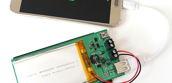
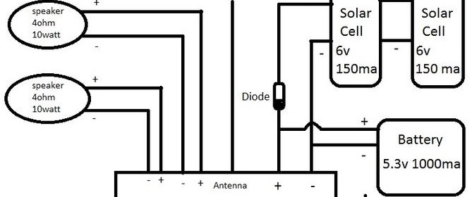
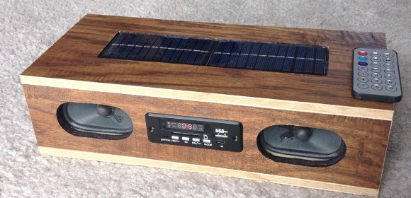
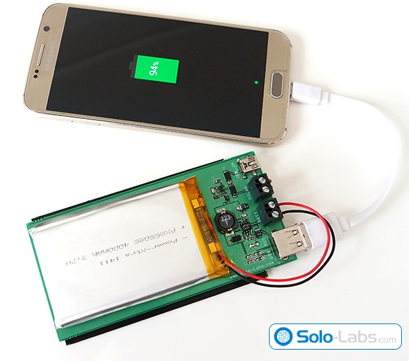
Solo-lab’s new project article is about building a rechargeable USB power bank which harvests energy by using a solar panel. It uses a 3.7V, 4000mAh LiPo battery to store the electric energy generated by the solar panel. The LiPo charging circuit is based on MCP73831, which is a miniature single cell, fully integrated LiPo charge manament controller. The output of the battery is converted to 5V using a step up converter based on LT1302-5. The 5V output is available via USB ports.

Solar powered USB power bank

Solar powered USB power bank

MCP73831 is miniature single-cell, fully integrated Li-Ion,Li-Po charge management controller. Since the input voltage range is 3.75V to 6V, any solar cell rated between these values can be used as the input source. An aditional 5V mini USB input is also included in the design which allows you to charge the power bank when sunlight is insufficient. The controller will charge the battery up to 4.2V safely. The led connected to the STAT input off the controller lights up during the entire charge process.

The output stage is a step up converter which converts the battery voltage to 5V. It is based on LT1302-5 fixed 5V DC/DC converter. The converted power is delivered to an A type female USB converter. The input voltage of LT1302-5 can be as low as 2.2V so your Li-Po battery should have internal low voltage cutoff circuitry. The solar panel used in the project is rated at 6V and 150mA which provides about 0.9W/h in ideal conditions and the Li-Po battery is rated at 3.7V and 4000mah which can deliver approximately 15W/h. We can see that charging will last much more than 15 hours because the efficiency of storage and step-up conversion will be less than 100% and the energy we can harvest from the sun depends on the time of the day and angle of the light beams. We can easily say that it will take days to fully charge the battery by using this solar panel. Since the solar energy is free, any percentage will be of profit.

Audio transmission using Laser

Armand & Victor did an interesting experiment about sending audio over a laser beam. They used a 250mW diode laser, modulated its output with an audio signal, and aimed the modulated beam to a solar cell located at more than 400 meters away. The output of the solar cell is directly fed to an high power amplifier to reconstruct the audio. You wouldn’t believe the demodulated audio was surprisingly good quality.

Rubidium standard real time clock for tracking local time dilation

According to General Relativity, we all experience finite amount of time dilation in our daily lives, depending upon our location, elevation, and velocity. At the speeds we travel at and the elevation we experience in everyday, time dilation is so small that it’s not detectable to us. But the high accuracy of atomic clocks have provided evidence for this effect even at our everyday speed. Cameron Meredith has shared an interesting project on Hackaday.io about using a rubidium atomic frequency standard to continuously track local time dilation effects relative to a reference GPS clock.

Rubidium standard RTC

Rubidium standard RTC

This project uses a rubidium atomic frequency standard to continuously track local time dilation effects relative to GPS, and eventually the WWVB US atomic clock radio frequency signal. The idea is to continuously monitor and record the cumulative time deviation. An I2C multiplexer board allows for more than one RTC module (Since these have a hard coded I2C address you can normally only use one). I went for three – One tracking GPS time, another tracking the rubidium standard, and the last one as a control or reference clock – without compensation.

Solar powered FM radio and mp3 player

Khaleel123 has posted an Instructable on how he built a solar-powered FM radio/mp3 player using some leftover wood flooring, salvaged pc speakers, four ni-cad rechargeable AA batteries, and inexpensive FM Radio/mp3 player module and solar panels that he bought on ebay. The FM radio module cost him less than $3 and is capable to play mp3 audio through an SD card or USB drive.

f5fpfcfitchfut8-large

Solar-powered FM radio and mp3 player

fhdavnxitchgbqh-large

Wiring connections between the radio module, speakers, solar cells and batteries


Khaleel123 writes,

The one I used has an operating voltage range between 5-12 and it is 4 ohm stable @ 3 watts rms x2. So knowing this its safe to use the following combination of components for the power source. Four rechargeable AA batteries in series which can be charged up to 5.8 volts but in our case will only get as high as 5.3 volts. Along with two 6 volt solar cells in parallel with a diode that drops the voltage .7v the total output of the solar cells is 5.3 volts at 300 ma. The diode is necessary to protect the cells from the power stored in the battery. The speakers are 4 ohms @ 10 watts so those are exactly within the recommended range for this type of module. The module did not come with any wires or antenna soldered to it, but was clearly marked and easy to solder to. Also the batteries had to be soldered to each other, as long as you scuff up the ends they can be soldered easily too. I just soldered on a around a foot of wire for the antenna then coiled it and hot glued it down. Hot glue was also used to secure the solar cells, speakers, and battery just because it was quick and easy to do it that way.

RGB audio visualizer using FPGA

Sam Miller, Sahil Gupta, and Mashrur Mohiuddin built a 64×64 RGB LED matrix audio visualizer as their final project for the ECE5760 Microcontroller Design course at Cornell. The visualizer responds to a musical input in real time with a graphic animation on the RGB panel using vertical bars, balls, and particle to enhance the user’s listening experience. The RGB visualizer runs off of an Altera DE2-115 FPGA, which handles all the controls and processing of data for the 64×64 LED Matrix as well as the beat detection and audio output.

Functional block diagram of RGB visualizer

Functional block diagram of RGB visualizer

royg_bars_square_fixed

Our system starts with a musical input from the 3.5mm line-in input from the FPGA. This analog input is fed through an ADC to digitize the signal at a sampling rate of 48kHz. This signal is fed back through a DAC to the line-out port into speakers in order to play the audio. After the ADC, the audio signal is separated into its frequency components through our FFT module. These frequency components are used in a beat detection algorithm to detect large changes in signal energy, which correspond to beats in the song. The bars mode of the visualizer uses the frequency components directly, while the ball and the particle mode only use the beat of the song. Each of these 3 modules uses their inputs to calculate the coordinates and corresponding colors of each LED in the matrix. The outputs of the modules are muxed and written to two buffers (since the matrix writes to two LEDs simultaneously). From here, another module reads the contents of the buffer, and drives the LED matrix via the GPIO pins on the FPGA.

« Older Entries Recent Entries »