Author Archives: R-B

VGA display using PIC Micro
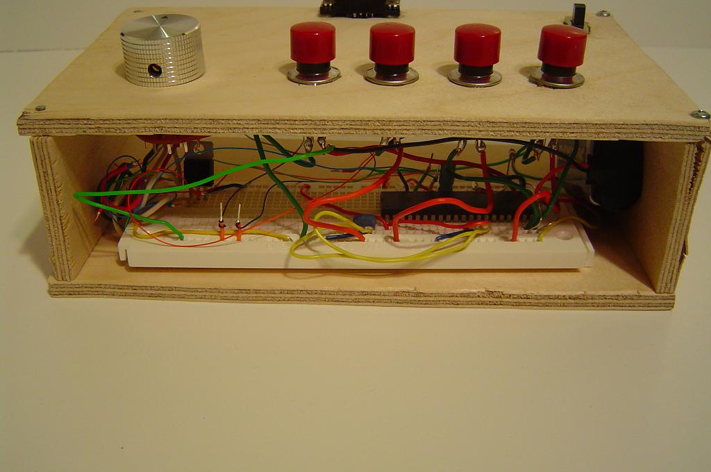
VGA stands for Video Graphics Array, which is a widely used analog interface between a computer and monitor that uses a 15-pin plug and socket. The VGA display requires accurate timing signals and synchronization. The goal of this project is to generate VGA signals using a PIC microcontroller to display characters, text and figures on a computer monitor.

It uses a PIC18F452 microcontroller running at 4 MHz external crystal to generate accurate timing signals to drive VGA pins. The software is written in assembly so that timing signals will be more accurate. The author also provides a brief introduction of VGA signals.
Read more

A brief tutorial on frequency measurements

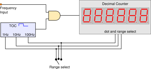
Measuring the frequency of a signal may seem to be a simple process of counting pulses, but in order to get better accuracy, few other things should be considered, such as the gating interval and the range of measurement. This tutorial, posted on the pcbheaven.com, briefly describes two typical methods of frequency measurement: Direct Frequency Measuring (DFM) and the Reverse Frequency Measuring (RFM), with their pros and cons.

The shape of the incoming signal may be distorted and of varying amplitude. Therefore, some sort of signal conditioning along with a voltage limiter is required prior to the frequency counter circuit.


Read More

Lab 7: PIC Timers and Counters (Part 1)

Description

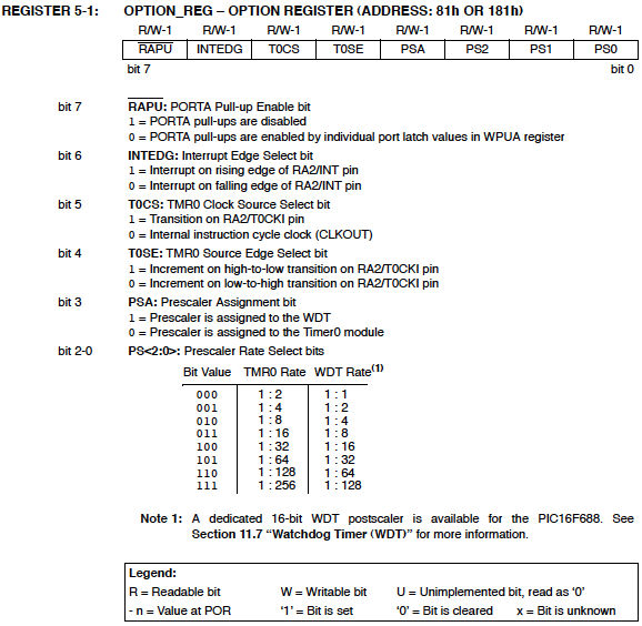
PIC microcontrollers are equipped with one or more precision timing systems known as Timers. They can be used to perform a variety of time precision functions, such as generating events at specific times, measuring the duration of an event, keeping date and time record, counting events, etc. The main component of a timer module is a free running binary counter that increments for each incoming pulse. Since it runs independently, it can count pulses concurrently with the main program execution. A PIC16F688 microcontroller has two built-in hardware timer modules: Timer0 and Timer1. Today’s lab lesson will explore the functionality of the Timer0 module.

Required Theory

The fundamental concept of a timer/counter module is discussed in Timers and Counters. It is simply an independent binary counter that can be configured to count instruction cycles or to count external clock pulses. The Timer0 module in a PIC16F688 microcontroller is an 8-bit synchronous counter that stores the value for the counter in the special function register called TMR0. This register can be read or written at any time by software. If you write a value to it, the counter will start incrementing from there.
Read more

A multifunction digital meter using Atmega128

This is a multifunction bench test instrument built using an Atmega128 microcontroller and incorporate a lot of functions like voltmeter, ammeter, logic analyzer, frequency generator, frequency counter and also provides regulated DC power supply.

This device is interfaced with a Windows PC to display the measurements. The PC software is developed in VB 6. The function generator is based on a MAX038 IC that can provide sine, triangle or square wave, with adjustable duty cycle, from about 1 Hz to > 20 MHz.
Read more

AVR digital clock with white seven segment LED display

This is a digital clock project based on an ATtiny26 microcontroller, displaying time on four seven segment LEDs. The seven segment LEDs glow bright white and are multiplexed through PORTB pins, whereas the segments are driven by PORTA pins. The time is normally shown in hh.mm format but it can be switched to display mm.ss too. The time setting can be done with two push button switches.

Read more

« Older Entries Recent Entries »