Author Archives: R-B

Low power temperature data logger using PIC18F27J53
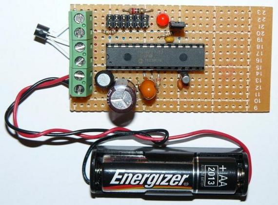
Most of the microcontroller based data loggers use external EEPROM chips for storing the measurement values. This increases the cost, power consumptionm, and the size of the circuit board. Instead, why don’t we choose a microcontroller with a larger flash memory and use it for storing the data. Actually, a data logger’s firmware is not very big in size. So, the remaining flash memory can be used to store the data from realtime measurements. This project is based on the same concept and uses a PIC18F27J53 microcontroller that has 128K programmable flash memory. The PIC18F27J53 family microcontrollers are low power and high performance 8-bit MCUs with Integrated full-Speed USB 2.0. They have Deep sleep mode feature for low power application, and a RTCC module for real time applications.The analog to digital converter (ADC) module is 12-bit, so it gives better resolution.

The beauty of this project is it runs with a single AA cell battery. Wait a minute, how that could be possible. The operating voltage for PIC18F27J53 is between 2-3.6 V, and an AA cell battery can only provide 1.5 V. Yes, it has a voltage booster circuit to up-convert the 1.5 V from the battery to the required voltage level. And the switching for the boost circuit is provided by the microcontroller’s PWM output itself. So, how does the microcontroller start at the beginning? Yes, it requires a jump start at the beginning. That can be done by simply supplying the power from a USB cable at the beginning, then the microcontroller will pick up the power from the battery itself. This is a very interesting project.

Read more

Calibrating a thermistor for temperature measurements

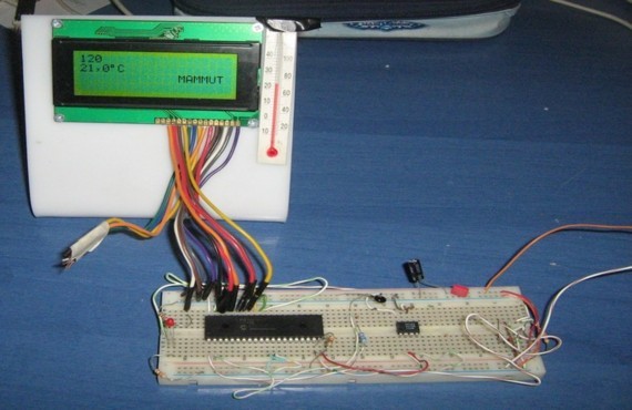
A thermistor is a passive device that changes its resistance with temperature. If the temperature-resistance characteristic is known, it can be used as a temperature sensor by measuring the resistance, or more precisely, the voltage across it. Thermistors are classified in to two types: NTC (negative temperature coefficient) and PTC (positive temperature coefficient). A NTC thermistor decreases its resistance while the temperature rises, and a PTC does the opposite.

Although the datasheet of a thermistor describes the temperature-resistance relationship, the measurement based on that is not very accurate. Therefore, you may need to calibrate it against a more accurate sensor. This article describes about calibrating a 10K thermistor against a DS1621 temperature sensor, which is a very precise digital temperature sensor. With a series of readings from both the sensor, you can see if the relationship between the temperature and resistance of the thermistor is linear or not.
Read more

Portable 2.4 GHz Spectrum Analyzer using Atmega8

There are plenty of wireless devices available on the market that broadcast in the 2.4 GHz ISM band. Such devices include Bluetooth, WiFi, Zigbee, wireless USB, cordless phones, wireless mice and keyboards, etc. This project describes a wireless spectrum analyzer to examine the surrounding radio frequencies in 2.4 GHz band.

The project is based on the Cypress’s CYWUSB6935 radio module. It is a complete radio module with PCB trace antenna and it operates in the unlicensed Industrial, Scientific, and Medical (ISM) band (2.4 GHz- 2.483 GHz). The radio module is interfaced with an Atmega8 microcontroller, and the recieved spectrum is displayed on a Nokia 3410 LCD. The microcontroller, the Nokia LCD module and the radio module are all operated at 3.3 V power supply. The firmware is developed in C using AVR GCC for Windows (WinAVR).
Read more

Lab 6: Seven segment display

Introduction

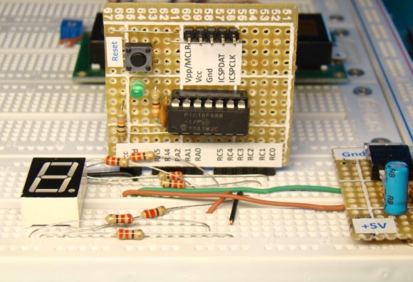
Seven segment LED displays are often found in clock radios, VCRs, microwave ovens, toys and many other household items. They are primarily used to display decimal numbers but they can also display a few alphabets and other characters. This experiment describes interfacing a seven segment LED display to a PIC16F688 microcontroller. You will make a hexadecimal counter that counts from 0 (00h) to 15 (0Fh) and display the value on the seven segment LED display.

Required Theory

A seven segment LED display is an special arrangement of 7 LED elements to form a rectangular shape using two vertical segments on each side with one horizontal segment on the top, middle, and bottom. By individually turning the segments on or off, numbers from 0 to 9 and some letters can be displayed. Seven segment displays sometime also have an eighth segment to display the decimal point. Therefore, a seven-segment display will require seven outputs from the microcontroller to display a number, and one more output if the decimal point is to be displayed too.

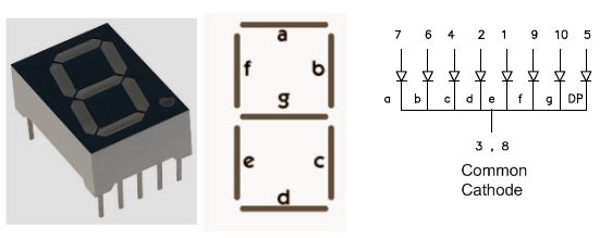
The segments are marked with non-capital letters: a, b, c, d, e, f, g and dp, where dp is the decimal point. The 8 LEDs inside the display can be arranged with a common cathode or common anode configuration. With a common cathode display, the cathodes of all the segment LEDs are tied together and this common point must be connected to the ground. A required LED segment is then turned on by applying a logic 1 to its anode. In common anode displays, all the anodes are tied together and the common anode is connected to the supply voltage Vcc. Individual segments are turned on by applying logic 0 to their cathodes.

When more than one seven segment display is used, a multiplexing technique is used to minimize the required number of microcontroller pins. We will discuss about that technique later.

In this experiment, a LT543 model common cathode seven segment display is used. The segment LEDs glow red when turned on. The module has 10 pins whose configuration is shown below.


Read more

Single button code entry for a digital lock

Yes, it has got just one push button to enter the code to unlock the system. The author demonstrates how you can just enter multiple code numbers in sequence from a single button input. If the code entered matches with the preset pass code, a relay is turned on.

This project uses a PIC16F628A microcontroller that monitors the user inputs from the single button. You can enter a number 3 by pressing the button 3 times. Every time you enter a number, the microcontroller acknowledges by lighting an LED. When you entered all the code numbers correctly in sequence, the relay is turned on. You can connect this system to your garage door opener, or to any other security lock. The another interesting part of this project is that you can even change the pass code with the same button. For more details, visit the author’s page down below.

Read more

« Older Entries Recent Entries »