Category Archives: PIC Projects


DIY 2.1 channel audio amplifier
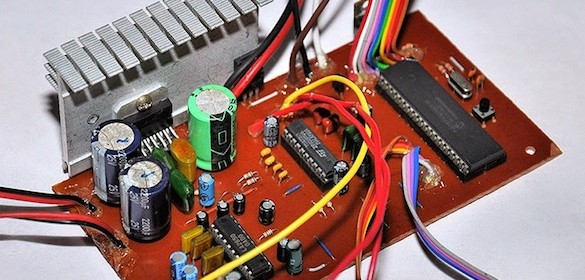
Dilshan Jayakody’s new project is a digitally-controlled 2.1 channel audio amplifier based on the TDA7377 AF power amplifier and PIC18F452 microcontroller. The amplifier provides 2 × 6W + 20W audio output power, ±14dB bass and treble controls, fully configurable +35dB bass booster for sub-woofer and satellite speakers and loudness switch.

Read more
Yet another LC meter using PIC16F628A

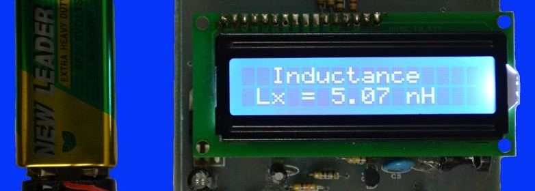
DIY LC meter projects are very popular among hobbyists and students. Here is another LC meter project which is based on PIC16F628A microcontroller. It uses a tank oscillator circuit combining a few external components and PIC’s internal comparator module. The L and C values are computed from the resonant frequency of the LC tank circuit. The project also incorporated auto-calibration by shorting the test leads. The meter uses a standard 2×16 character LCD for display.  

Read more

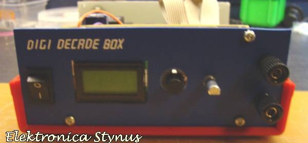
PIC Microcontroller based resistor decade box

The old resistor decade boxes consisted of a bunch of rotary switches which make them little bulky and expensive. Stynus has built this microcontroller-based resistor decade box that uses one rotary encoder and 16 relay switches to switch on the various resistances. The microcontroller used in this project is PIC16F84A.

Read more

PIC based count down timer

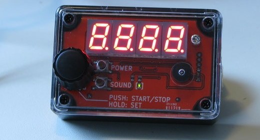
Here is another countdown timer based on the PIC16F886 microcontroller. The timer displays the time on four bright 7-segment LEDs, which are driven by a TLC5916 LED driver chip. The timer flashes the seven segment LEDs when the time is up. The timer settings are done with a rotary encoder with a push button, and gets powered from two AAA batteries.

Read more

PIC12F683 based battery charger

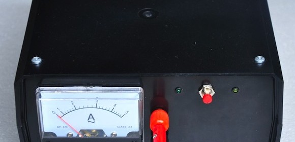
Here’s an Instructable about a DIY charger for car’s battery with an analog DC ammeter in the front panel. A PIC12F683-based control circuit is enclosed inside which adds some intelligence to this charger. The PIC MCU checks the terminal voltage of the battery being charged in every ten minutes using one of its analog inputs, and if it is found above a set threshold, the charging process is stopped. A relay switch is included into the circuit to connect/disconnect the charger output and the battery terminals.

Read more
« Older Entries Recent Entries »