Category Archives: PIC Tutorials


Getting started with PIC18F Microcontrollers
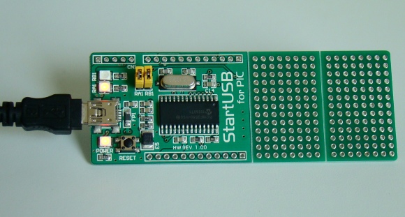
After writing quite a bit of experimental tutorials on PIC16F series of microcontrollers, I thought of moving forward to the enhanced-range family of PIC microcontrollers, the PIC18F, which was introduced by Microchip in late 90s. Although PIC16F series are excellent general purpose microcontrollers, certain limitations have emerged, such as, they have limited program and data memory, their stack size is small, and all the interrupt sources have to share a single interrupt vector. Their limited instruction set also doesn’t provide direct support for more advanced peripherals interfaces like USB and CAN. The basis of the PIC18F Series is to address

Read more
Lab 11: Multiplexing seven segment LED displays

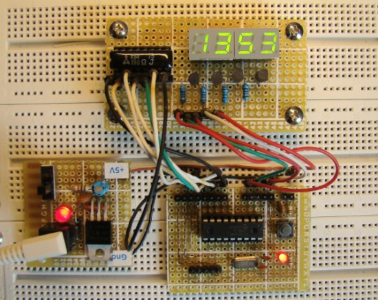
In Lab 6, we discussed about interfacing a seven segment LED display to a PIC microcontroller. The seven segments were driven individually through separate I/O pins of the microcontroller. If we do just like that then for 4 seven segment LED displays, 28 I/O pins will be required, which is quite a bit of resources and is not affordable by mid-range PIC microcontrollers. That’s why a multiplexing technique is used for driving multiple seven segment displays. This tutorial shows how to multiplex 4 common anode type seven segment LED displays with a PIC16F628A microcontroller.

Read more

Lab 10: DC motor interfacing to PICMicro

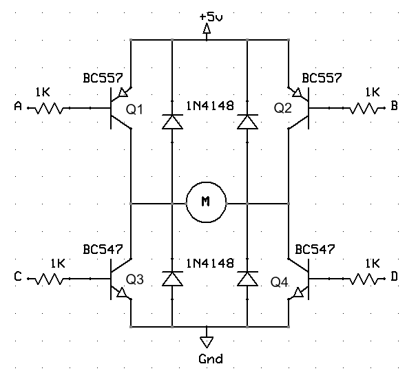
Description Perhaps one of the most entertaining things to do with an embedded microcontroller is to get it to actually move something. Three very popular devices used to “make things move” include dc motors, RC servos, and stepper motors. This lab session will look at how you can interface a dc motor to a PIC microcontroller. Required Theory DC motors are simple two-lead, electrically controlled devices that convert electrical power into mechanical power through the interaction of two magnetic fields. One field is usually produced by a stationary permanent magnet (on the stator), and the other field is produced by

Read more

Lab 9: Pulse Width Modulation (PWM) using PIC CCP module

Description Pulse width modulation (PWM) is a technique of controlling the amount of power delivered to an electronic load using an on-off digital signal. The fraction of the period for which the signal is on is known as the duty cycle. The average DC value of the signal can be varied by varying the duty cycle. The duty cycle can be anywhere between 0 (signal is always off) to 1 (signal is constantly on). Suppose, if the signal has +5 V while it is on and 0 V during off condition, then by changing the duty cycle of the signal,

Read more

Lab 8: Asynchronous serial communication

Description The PIC16F628A microcontroller has a built in Universal Synchronous Asynchronous Receiver Transmitter (USART) hardware that allows to communicate with a wide range of serial devices such as memory chips, LCDs, personal computers, etc. The USART module has two modes of operation: synchronous (requires a synchronized clock between the transmitter and receiver) and asynchronous (no synchronization clock required). As the asynchronous mode is more popular, we will focus today’s lab session on this and will establish a two way serial data link between the PIC microcontroller and a PC. Required Theory Serial communications are used in microcontroller-based systems, mostly due

Read more
« Older Entries Recent Entries »