Category Archives: Tips and Tricks


Lab 11: Multiplexing seven segment LED displays
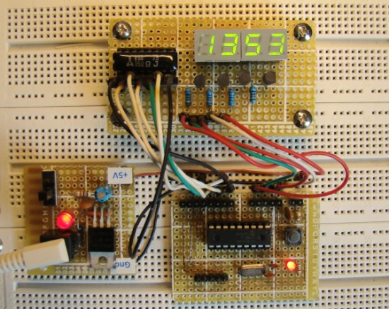
In Lab 6, we discussed about interfacing a seven segment LED display to a PIC microcontroller. The seven segments were driven individually through separate I/O pins of the microcontroller. If we do just like that then for 4 seven segment LED displays, 28 I/O pins will be required, which is quite a bit of resources and is not affordable by mid-range PIC microcontrollers. That’s why a multiplexing technique is used for driving multiple seven segment displays. This tutorial shows how to multiplex 4 common anode type seven segment LED displays with a PIC16F628A microcontroller.

Read more
Commandments for using PIC Microcontrollers

Based on his working experience with PIC microcontrollers, John Chandler has summarized some basic rules that could minimize the project development time and increase the reliability of PIC operation. Some of these rules (he said commandments) are related to power supply, clock and reset operation and hence they are applicable to all PIC circuits. Some PIC microcontrollers have multiple pins for Vcc and ground. He suggests to connect all of them not just one pair. A 0.1 uF bypass capacitor must be connected closest to the microcontroller. Similarly, the MCLR pin must not be floating, if it is enabled. Read more

Read more

How to measure dc current with a microcontroller?

Microcontrollers usually don’t have specific ports for measuring currents, but they do have ADC channels through which you can measure analog voltages of a certain range. This means a dc current can be indirectly measured by a microcontroller’s ADC channel by first converting the current into voltage. The simplest way of doing this is to place a resistance in series with the current path and measure the voltage drop across it. But hold on, if you place an additional resistance in the circuit, it will affect the original current. Therefore, we need to use a very small value resistance so

Read more

2-Wire Keypad Interface Using a 555 Timer

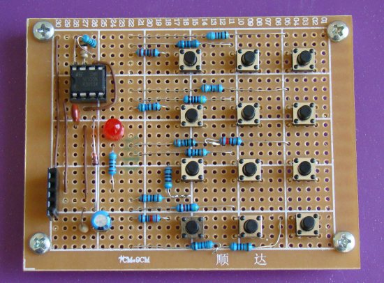
Keypads are a very commonly used input device in microcontroller-based systems. In a keypad, multiple switches are arranged in rows and columns so that they could be interfaced to a microcontroller with a minimum number of I/O pins. For example, a 12-key keypad is arranged in a 4×3 format, which allows to interface the 12 keys to a microcontroller with only 7 connections. The location of each key on the keypad is defined by two coordinates: the row and the column. When a key is pressed, it connects its row with its column. The microcontroller must scan all the rows

Read more

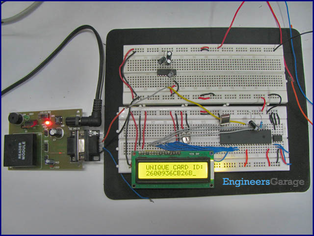
Radio frequency identification (RFID) with a microcontroller

RFID is a technology that uses radio waves for transmitting the identity (unique serial number) of an object or a person. If you have an electronic key to access your office building, it probably uses the same technology. An RFID system has a reader and a transponder (also called tag). The reader transmits electromagnectic waves in its surrounding through an antenna system, and when a tag passes passes through the zone, it is activated and the reader can read the identification data stored inside the electronic tag.

Read more
« Older Entries Recent Entries »