Intelligent temperature monitoring and control system using AVR microcontroller
|
|
Controlling temperature has been a prime objective in various applications including refrigerators, air conditioners, air coolers, heaters, industrial temperature conditioning and so on. Temperature controllers vary in their complexities and algorithms. Some of these use simple control techniques like simple on-off control while others use complex Proportional Integral Derivative (PID) or fuzzy logic algorithms. In this project I’m going to discuss about a simple control algorithm and utilize it intelligently unlike analogue controllers. Here are the features of our controller:
- Audio-visual setup for setting temperature limits.
- Fault detection and evasive action.
- Temperature monitoring and display.
- Audio-visual warning.
- System status.
- Settable time frame.
- Data retention with internal EEPROM memory.
For this design I used an ATMega32L AVR microcontroller with an internal clock frequency of 8MHz, a 4×20 LCD for presenting data visually, a 4-button input interface, a tiny piezo sounder for audible indications and some LEDs for showing faults and simulating real-life devices like heater and coolers. I used MikroC for AVR compiler from Mikroelektronika to develop the firmware for this controller.
Hardware
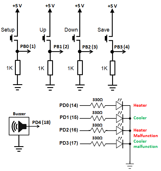
The hardware consists of a four-button interface, four LEDs, a piezo tweeter or sounder, a 4×20 LCD, a LM35 temperature sensor, an AVR ATMega32L microcontroller and some other passive parts. Two LEDs connected to PORTD0 and PORTD1 pins simulate on and off operation of relay switches that are actually present in actual applications to control a heater and an air conditioner. The hardware is powered by a 5V source preferably with a 5V regulator like 7805. If relays are used then a 12/24V source will also be needed to power the relays. The AVR micro’s AVREF and AVCC pins should be both connected to the 5V source. The distance between the LM35 sensor and the AVRs ADC pin must not be greater than 10-12cm for proper temperature reading. Though I did this project in a prototyping board made with a strip board, a PCB version is more preferred. Two additional LEDs connected to PD2 and PD3 indicates the failure or malfunctioning status of the air conditioner and the heater.
Firmware
The entire firmware relies on logical decisions at every step. I wrote the code in a way that the complete code is divided into understandable small functional blocks or functions. Each of these functions is doing specific tasks.
Starting from the top of the code, I declared some definitions of port pins, LCD pins and EEPROM locations. Next I declared global variables and function prototypes.
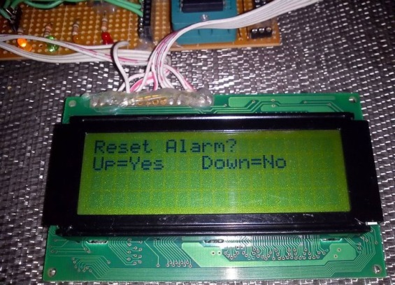
I’m now going to explain the tasks each functions do. The first function that’s called in the main() function is the setup_mcu() function. It configures the I/O ports for general tasks, LCD and audio output pin. It also sets flags “c” and “h” zero. These flags are set whenever the system faces an alarm. “h” means heater fault flag and “c” means cooler fault flag. Next to the setup_mcu() function is the scan_keys() function which simple reads the buttons and a generate specific tone for the key pressed and return a specific value for that particular key. Thus key press, key debouncing delays and tone generation accompanied with key press is made universal throughout the entire code. The adc_avg() function takes 64 samples of channel 0 of the AVR’s built-in ADC and makes the average of these samples to reduce noise and ensure accuracy. This function returns an unsigned long value since 10-bit ADC resolution is used. Following the adc_avg() function is the temperature display function temp_display(). All it does is simply show the current value of the temperature on the LCD display. The settings() function is the most important part of the program. When entered this function has two menus. The first one according to the program is the reset fault service request and the second allows the user to setup the high and low temperature values along with the number of passes that will be allowed for the temperature to reach the nominal value. Whenever these values are exceeded an alarm goes high and a particular temperature control device (heater or cooler) is set. Thus setting the right values ensure proper system operation and avoid false alarms. The inc_dec function is used for the menu operations whenever when we need to change a value. It is called to setup temperature values and pass values. The display_common function is used for common display purposes as needed in the inc_dec function. Next the compare_temp() routine compares temperature and shows a message in the LCD if the temperature is within limit or beyond limit. Another important part of the program is the function called controller_state. It is here the controller sets on or off the temperature control devices and also generates alarm in the event of any error. Associated with this routine is the check_fault routine when the conditions for fault are checked. The read_memory routine reads the stored data for temperature limits and others in the AVR internal EEPROM. Finally the last three functions of the code are fault_messages() which shows the fault type, light the specific LED the specific fault and generate a warning tone for all faults; settings_demanded() calls for settings menu and all_tasks() is the collection of all the tasks done in the main function.
Here’s the complete mikroC AVR code:
#define setup PINB0_bit #define up PINB1_bit #define down PINB2_bit #define save PINB3_bit #define heater PORTD0_bit #define cooler PORTD1_bit #define Fault_H PORTD2_bit #define Fault_C PORTD3_bit #define ee_t_high 0x0 #define ee_t_low 0x4 #define ee_t_delta 0x8 #define ee_pass_times 0xE sbit LCD_RS at PORTC2_bit; sbit LCD_EN at PORTC3_bit; sbit LCD_D4 at PORTC4_bit; sbit LCD_D5 at PORTC5_bit; sbit LCD_D6 at PORTC6_bit; sbit LCD_D7 at PORTC7_bit; sbit LCD_RS_Direction at DDC2_bit; sbit LCD_EN_Direction at DDC3_bit; sbit LCD_D4_Direction at DDC4_bit; sbit LCD_D5_Direction at DDC5_bit; sbit LCD_D6_Direction at DDC6_bit; sbit LCD_D7_Direction at DDC7_bit; bit h; bit c; float t=0.0; float temp=0.0; unsigned long pass=0; unsigned int t_low=0; unsigned int t_high=0; unsigned int t_delta=0; unsigned char pass_times=0; void setup_mcu(); unsigned char scan_keys(); unsigned long adc_avg(); void temp_display(); void settings(); signed int inc_dec(signed int variable,signed int max,signed int min,unsigned char x,unsigned char y); void display_common(unsigned char x,unsigned char y,unsigned char convert); void compare_temp(); void controller_state(unsigned short state); void check_fault(unsigned short stat); void read_memory(); void fault_messages(); void settings_demanded(); void all_tasks(); void main() { setup_mcu(); read_memory(); while(1) { all_tasks(); }; } void setup_mcu() { Lcd_Init(); Sound_Init(&PORTD,4); Lcd_Cmd(_LCD_CLEAR); Lcd_Cmd(_LCD_CURSOR_OFF); DDRD=0xFF; PORTD=0x00; DDRB=0x00; c=0; h=0; } unsigned char scan_keys() { if(setup) { Sound_Play(888,99); return 1; } else if(up) { Sound_Play(900,9); return 2; } else if(down) { Sound_Play(700,9); return 3; } else if(save) { Sound_Play(800,99); return 4; } else { return 0; } } unsigned long adc_avg() { unsigned char sample=0; register unsigned int adc=0; for(sample=0;sample<64;sample++) { adc+=((float)ADC_Read(0)); delay_us(20); } adc=adc>>6; return adc; } void temp_display() { register unsigned long conv=0; unsigned char ch=0; t=((adc_avg())*48.9); temp=(t*0.01); conv=t; ch=(conv/1000); Lcd_Chr(2,1,(48+ch)); ch=((conv/100)%10); Lcd_Chr_CP((48+ch)); Lcd_Chr_CP(46); ch=(conv/10)%10; Lcd_Chr_CP(48+ch); ch=(conv)%10; Lcd_Chr_CP(48+ch); Lcd_Out_CP("'C"); Delay_ms(100); } void settings() { Lcd_Cmd(_LCD_CLEAR); read_memory(); if(h||c) { lcd_out(1,1,"Reset Alarm? "); lcd_out(2,1,"Up=Yes Down=No"); do { if(scan_keys()==2) { c=0; h=0; break; } if(scan_keys()==3) { break; } }while(1); } Lcd_Cmd(_LCD_CLEAR); delay_ms(500); lcd_out(1,1,"Settings Step 1/3 "); lcd_out(2,1,"High Temp. Limit:"); lcd_out(3,4,"'C"); t_high = inc_dec(t_high,99,0,1,3); if((t_high>=0)&&(t_high<=99)) { eeprom_write(ee_t_high,t_high); Lcd_Cmd(_LCD_CLEAR); } delay_ms(500); lcd_out(1,1,"Settings Step 2/3"); lcd_out(2,1,"Low Temp. Limit:"); lcd_out(3,4,"'C"); t_low=inc_dec(t_low,99,0,1,3); if(t_low>=0 && t_low<=99) { eeprom_write(ee_t_low,t_low); Lcd_Cmd(_LCD_CLEAR); } delay_ms(500); lcd_out(1,1,"Settings Step 3/3"); lcd_out(2,1,"No. of passes: "); pass_times=inc_dec(pass_times,99,0,1,3); if(pass_times>=0 && pass_times<=99) { eeprom_write(ee_pass_times,pass_times); Lcd_Cmd(_LCD_CLEAR); } delay_ms(500); pass_times=(eeprom_read(ee_pass_times)); t_high=(eeprom_read(ee_t_high)); t_low=(eeprom_read(ee_t_low)); t_delta=(((t_high-t_low)/2)); eeprom_write(ee_t_delta,t_delta); delay_ms(100); } signed int inc_dec(signed int variable,signed int max,signed int min,unsigned char x,unsigned char y) { do { display_common(x,y,variable); if(scan_keys()==2) { variable+=1; } if(scan_keys()==3) { variable-=1; } if(variable>max) { variable=min; } if(variable<min) { variable=max; } if(scan_keys()==4) { return variable; } if(scan_keys()==1) { return (max+1); } }while(1); } void display_common(unsigned char x,unsigned char y,unsigned char convert) { unsigned char t = 0; t=(convert/10); Lcd_Chr(y,x,(48+t)); t=(convert%10); Lcd_Chr(y,(++x),(48+t)); } void compare_temp() { if(temp>=t_high) { Lcd_Out(3,1,"High Temperature!"); controller_state(1); } if(temp<=t_low) { Lcd_Out(3,1,"Low Temperature! "); controller_state(2); } if(((temp<t_high)&&temp>=(t_high-t_delta))||((temp>t_low)&&temp<(t_delta+t_low))) { Lcd_Out(3,1,"Within Limit. "); controller_state(0); } } void controller_state(unsigned short state) { if(state==1) { if(c==0) { heater=0; cooler=1; check_fault(1); } } else if(state==2) { if(h==0) { heater=1; cooler=0; check_fault(2); } } else { heater=0; cooler=0; } } void check_fault(unsigned short stat) { if(stat==1) { pass++; if((temp>=t_high)&&(pass==(pass_times*10))) { Fault_C=1; c=1; heater=0; cooler=0; pass=0; } if((temp<=(t_high-t_delta))&&(pass==(pass_times*10))) { heater=0; cooler=0; c=0; pass=0; } } if(stat==2) { pass++; if((temp<=t_low)&&(pass==(pass_times*10))) { Fault_H=1; h=1; heater=0; cooler=0; pass=0; } if((temp>(t_low+t_delta))&&(pass==(pass_times*10))) { heater=0; cooler=0; h=0; pass=0; } } delay_ms(100); } void read_memory() { pass_times=(eeprom_read(ee_pass_times)); delay_ms(30); t_high=(eeprom_read(ee_t_high)); delay_ms(30); t_low=(eeprom_read(ee_t_low)); delay_ms(30); if(pass_times>99) { eeprom_write(ee_pass_times, 45); delay_ms(30); pass_times=(eeprom_read(ee_pass_times)); delay_ms(30); } if(t_high>99) { eeprom_write(ee_t_high, 40); delay_ms(30); t_high=(eeprom_read(ee_t_high)); delay_ms(30); } if(t_low>99) { eeprom_write(ee_t_low, 20); delay_ms(30); t_low=(eeprom_read(ee_t_low)); delay_ms(30); } t_delta=(((t_high-t_low)/2)); eeprom_write(ee_t_delta,t_delta); delay_ms(30); } void fault_messages() { if((h==0) && (c==0)) { Lcd_Out(4,1,"System Okay. "); Fault_C=0; Fault_H=0; } if((h==1) || (c==1)) { Sound_Play(550,150); if((h==1) && (c==0)) { Lcd_Out(4,1,"Alarm! Heater Fault."); delay_ms(600); } else if((h==0) && (c==1)) { Lcd_Out(4,1,"Alarm! Cooler Fault."); delay_ms(600); } else if((h==1) && (c==1)) { Lcd_Out(4,1,"System Failed. "); delay_ms(600); } } } void settings_demanded() { if(scan_keys()==1) { delay_ms(9); while(scan_keys()==1); settings(); }; } void all_tasks() { Lcd_Out(1,1,"Active Temperature: "); temp_display(); fault_messages(); settings_demanded(); compare_temp(); } |
Operation
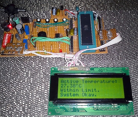
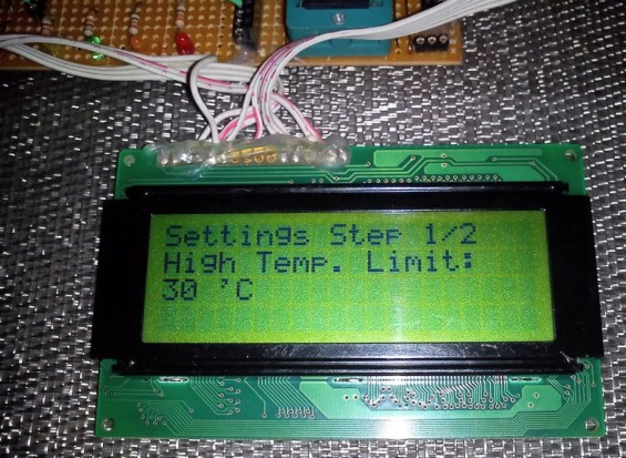
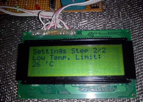
The system works as described here. Upon start-up the system sets up the required internal hardware of the AVR micro and then read the EEPROM memory. If the EEPROM locations contain garbage values then they are set with default values otherwise the previously stored values are read. After reading the EEPROM, the system starts to monitor temperature and waits for actions if any temperature limit is exceeded. The system at this point shows current temperature and system status. If the user wishes to set parameters then he/she has to press the setup button and enter the settings menu. In the settings menu there are three settings and these are high and low temperature limits and the number of passes the system will make prior to issuing a fault message. If, for example, the high temperature limit is set to 40?C, the low temperature limit is set to 20?C and the number of system passes is set to 45, and the current temperature gradually rises to 41?C from 30?C, the system will trip high temperature alarm and start the cooler. The LCD display will show high temperature alarm. Now if the temperature starts to decline and reach a value in between (40?C – (40?C -20?C)/2) =30?C [i.e t_delta] and 20?C within the 45 system passes then the cooler is turned off and no fault message is generated. The system resumes to normal state. If the temperature didn’t decline to the range mentioned as above then it is assumed that the cooler is either faulty or some other thing is causing too much heat generation which is exceeding the cooler’s capacity. Thus a fault warning is issued for the cooler and it is shut down until the fault has been cleared. In this way both the hardware and the cooler is protected from damage. The same scenario happens during the low temperature alarm. If both the cooler and the heater fail then the system goes in a complete halt state until reset or given attention.
This project was written by Shawon Shahryiar from Bangladesh. He works as an Engineer in the Research and Development Cell at ELECTRO Group in Dhaka. If you have any questions or concerns regarding this project, you can contact him at: |
 |
|
|




what library i used to run this source code?
the code doesn’t run what library i will use?
Very nice… Now let me say I want to control humidity also, for instance between 30% to 50%. How will I do that? thank you for your help
olá amigo!
muito bom o projeto, porem quando tento compilar o código fonte, alguns erros de compilação estão sendo retornados.
a primeira mensagem retornada é a seguinte: 69 324 Undeclared identifier ‘amp’ in expression TermostatoInteligente.c
você teria uma dica do que esta errado, porque esse erro sendo que o seu código compilou e vc conseguiu gerar o arquivo HEX?
Intelligent temperature monitoring and control system using AVR microcontroller
HELLO SIR ,,,
I AM FACING THE PROBLEM IN THIS PROJECT
NO DISPLY AND I AM USING ATMEGE32A
SO PLZ HELP ME ABOUT THIS
PLZ SEND UR CONTECT NUMBER
nice work boss,..nway do you happen to hv a complete curcuit arrangemnt of all you componants.
useful
Fantastic work
Hello ! nice tutorial sir. I want to do my B.E final year project on Fuzzy Logic and have read many books on it but you have shown best implementation. Sir it seems that Fuzzy Logic is just a bunch of “IF” statements nothing else .. am i right ? .. What is the significance of it then?
Pingback: ????????????? ?????????? ?? ATMega32
impressive piece of work! Just Amazing!
Pingback: Intelligent temperature monitoring and control system using AVR microcontroller / Cooking Hacks Blog
Pingback: La semana en links (09/08/2012) | Automatismos Mar del Plata