Regulated Power Supply for Your Breadboard
|
|
Embedded systems require electric power to operate. Most of the components in them including the processors can operate at a wide range of voltages. For example, the operating voltage range for PIC16F688 is from 2 to 5.5 V. It means you can supply power from three AA size batteries (4.5 V) and it will work just fine as long as the battery voltage doesn’t fall below 2 V. But there are certain applications where you need a regulated constant voltage for safer operation of the embedded system. For instance, any application that uses analog-to-digital converters (ADCs). ADCs require a fixed reference voltage to provide accurate digital count for input analog signal. If the reference voltage is not stable, the ADC output is meaningless. So, today we are going to make a regulated +5V power source for our lab.
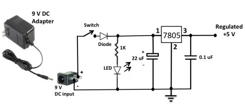
An LM7805 linear regulator IC is used for this purpose. It converts a DC input voltage of range 7-25 V to a stable +5 V. It requires just two external capacitors and is very easy to use, as shown below.
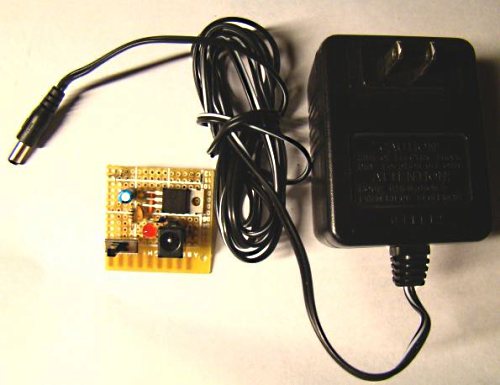
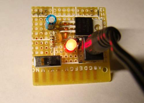
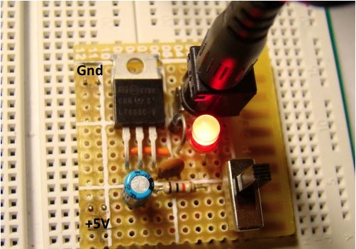
The input DC voltage for LM7805 could be obtained from a 9V DC wall adapter that can supply 1 Amp of load current. Actually, 12 to 24 V adapter will work too, but the LM7805 regulator dissipates an extreme amount of heat energy at higher input voltages and, therefore, requires a bulky heat sink. The wall adapter is chosen because it is cheap, easily available (you might already have got a spare one at home), and safe (the high voltage mains AC is isolated). You can solder this circuit on a general purpose prototyping board. Here are some pictures I took of my power supply unit.
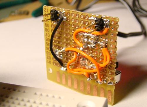
I have soldered male header pins (shown above) to +5 V and Gnd terminals so that the power supply unit can be plugged into the breadboard (shown below).
The power supply unit is ready now. Measure the output voltage with a digital multimeter and see how close is it to +5 V.
|
|

Sorry, can I use the usb port of the computer instead of the wall adapter and the circuit?. I have a master prog programmer and I use the lines of vss/vdd to supply the power to the whole circuit, is that correct?
I need how to make a clap switch with thermal sensor
useful post,Raj.
@ tushar …..do u still have this project now…need damn urgent bro…..
vous avez un très bon site.Vos réalisations sont excellentes.
Bon courage!
please sir
i have dc adapter 15v and i want to put both l 7812 and 7805
i want to know the capacitors need for l 7812 and l 7805
please can you help me
If I wanted to add a connector for a 9V battery, and allow it to run off of battery power or the dc adapter, how would I do that? Thanks.
Very useful information. i intend to do project where by the motion detector triggers a cell phone instead of abuzzer.Any information on how i can interface the detector to a cell phone is highl appreciated. please help. thank you
It’s really a nice and helpful piece of information. I’m glad that you shared this helpful info with us. Please keep us informed like this. Thanks for sharing.