Lab 9: Pulse Width Modulation (PWM) using PIC CCP module
|
|
Description
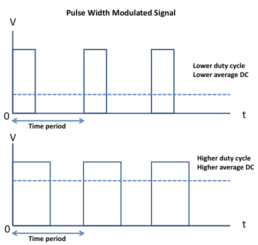
Pulse width modulation (PWM) is a technique of controlling the amount of power delivered to an electronic load using an on-off digital signal. The fraction of the period for which the signal is on is known as the duty cycle. The average DC value of the signal can be varied by varying the duty cycle. The duty cycle can be anywhere between 0 (signal is always off) to 1 (signal is constantly on). Suppose, if the signal has +5 V while it is on and 0 V during off condition, then by changing the duty cycle of the signal, any voltage between 0-5 V can be simulated. This method is commonly used for controlling speeds of DC motors and brightness of lamps. This lab session will talk about how to generate a PWM signal using the PIC16F628A microcontroller and control the brightness of an LED with it. PIC16F628A has a built-in hardware, called Capture/Compare/PWM (CCP) module, to generate a PWM signal.
Theory
The Capture/Compare/PWM (CCP) module in the PIC16F628A microcontroller is very versatile. The Capture and Compare features integrate closely with the 16-bit TMR1 and the PWM feature uses the third timer, the 8-bit TMR2. The CCP module has two 8-bit registers, called CCPR1L and CCPR1H. Together they form a 16-bit register that can be used for capture, compare or to form the duty cycle of a PWM stream. The CCP module is controlled by the CCP1CON register.
In Capture mode, the CCPR1L and CCPR1H registers record the 16-bit value of the TMR1 register when an event occurs on pin RB3/CCP1. An event can take place on:
- Every falling edge
- Every rising edge
- Every 4th rising edge
- Every 16th rising edge
The RB3/CCP1 pin must be configured as an input and Timer1 must be in Timer mode or synchronized Counter mode for this to work. A Capture event can also trigger an interrupt.
In Compare mode, the value of the TMR1 register is continuously compared to the value of the 16-bit register made up of CCPR1H and CCPR1L. When a match occurs, the RB3/CCP1 pin is driven high, low or remains unchanged, depending upon the setting of the CCP1CON register. The RB3/CCP1 pin must be configured as an output by clearing the corresponding TRISB bit. The Capture and Compare modes will be discussed later in more detail.
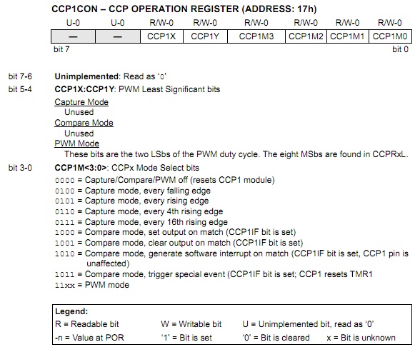
In PWM mode, the RB3/CCP1 pin can output a 10-bit resolution periodic digital waveform with programmable period and duty cycle. To operate in PWM mode, the CCP1 pin must be configured for output. The duty cycle of the waveform to be generated is a 10-bit value of which the upper eight bits are stored in the CCPR1L register, whereas the lowest two bits are stored in bit 5 and bit 4 of the CCP1CON register.
Circuit
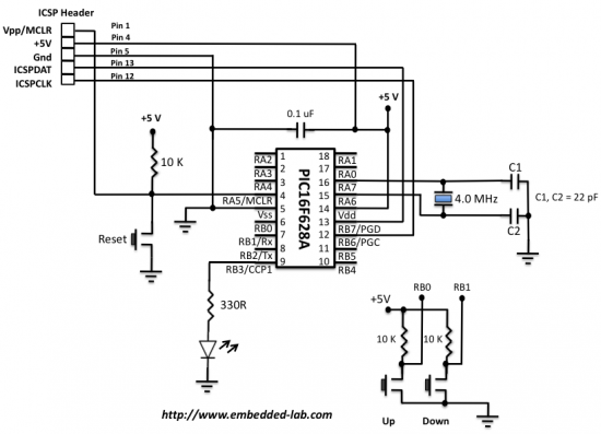
The setup for this experiment is very simple. Two tact switches are connected to pins RB0 and RB1 to provide inputs. An LED is driven by the PWM output from the RB3/CCP1 pin through a current limit resistor of 330R. The duty cycle of the output PWM signal is increased or decreased with the two tact switch inputs, and that will vary the brightness of the LED.
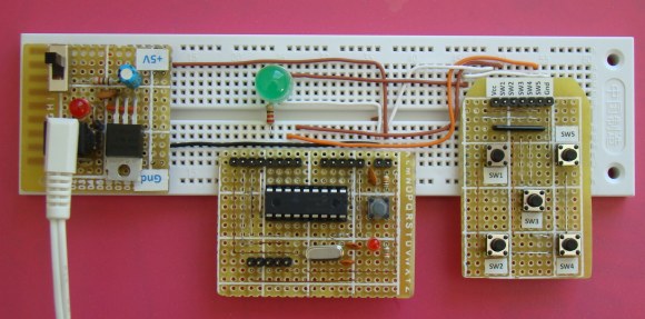
Circuit setup on breadboard
Software
The MikroC Pro for PIC compiler provides four library routines for controlling the PWM operation using the CCP module. They are PWM1_Init(const long frequency), PWM1_Set_Duty(unsigned short duty_ratio), PWM1_Start(void), and PWM_Stop(void). Read the MikroC manual for further details. The following program gives 10 different brightness levels of LED by varying the duty cycle from 0 to 250 in the step of 25. The duty cycle will be varied by pressing the UP and DOWN tact switches.
/*
 Lab 9: Pulse Width Modulation
 Copyright @ Rajendra Bhatt, 2010.
 Description: CCP module generating PWM
 MCU: PIC16F628A
 Oscillator: XT, 4.0 MHz, MCLR Enabled
*/
 sbit UP at RB0_bit;
 sbit DOWN at RB1_bit;
 unsigned short new_DC, current_DC;

 void debounce(){
  Delay_ms(300);
 }

 void main() {
 CMCON = 0x07; // Disable comparators
 PORTB = 0x00;
 TRISB = 0b00000011; // RB0, RB1 input, RB3 (PWM1) output
 PWM1_Init(5000);    // PWM module initialization (5KHz)
 new_DC = 0;         // Initial value of variable Duty Cycle
 current_DC = 0;
 PWM1_Start();       // Start PWM1 module with Zero DC
 PWM1_Set_Duty(current_DC);
 do {
  if (!UP){      // If the button connected to RB0 is pressed
   debounce();
   if (new_DC < 250)      // Don't go above 250
   new_DC = new_DC + 25 ; // increment Duty Cycle by 25
  }
  if (!DOWN) {   // If the button connected to RB1 is pressed
   debounce();
   if (new_DC !=0)        // Don't go below 0
   new_DC= new_DC - 25 ; // Decrement Duty Cycle by 25
  }
  if (current_DC != new_DC) {
   current_DC = new_DC ;
   PWM1_Set_Duty(current_DC); // Change the current DC to new value
  }
 } while(1);
}  // END main()
Download complete source and HEX files
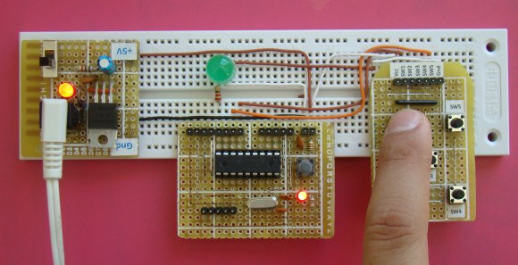
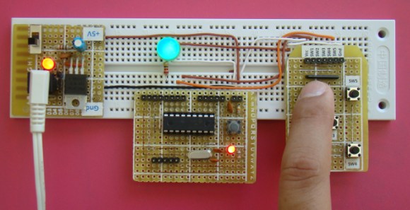
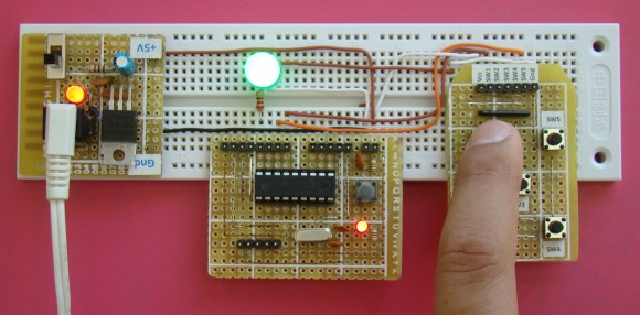
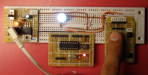
As the circuit is powered, the LED starts with zero brightness, i.e., zero duty cycle. Pressing the UP button increases the duty cycle and the LED will glow. The LED will brighten more and more on every press of the UP button, until the duty cycle reaches close to 1.
0% Duty Cycle
25 % Duty Cycle
50% Duty Cycle
~ 100% Duty Cycle
|
|

How to make LED brighter with 1000 hz?
Can you give me a code plss! Need help
When I use pwm..pins assigned to other tasks…is there any special thing to enable or disable while using pwm
Pins assigned to other tasks..stop working
What should be connected to pin12 &13 of the pic?
Dear Sir,
I assembled the same circuit and used same program. I have some problem with this circuit.
when i continue to press up button brightness of led increases, when it reaches at its highest brightness it should stop at that point even if I continue to press up button. But when Led at its highest point and I press up button brightness goes to lowest level again..
Please help me to fix this problem.
Can some send me de code for a the pic16f877a, i have problems when i try to generate the code, i really appreciate the help
Thanks for any other wonderful post. Where else may anyone get that type of
info in such a perfect manner of writing? I’ve a presentation next week, and I am at the look for such information.
hi, can you help me with the program for PIC16F877A by applying the same concept to control the brightness of LED. thanks
Hey could anyone help me, i want to control a servo motor with the PIC16F877A using the CCP1 output, thx !
can you add a blinking effect in it with about a 3Hz frequency at max luminescence with all the currently available fuctions?
Regards
can you add a blinking effect with about frequency of 3Hz? If yes then how.
Regards
hi?
can you help me on how to produce the frequency of 1Hz using pwm module of PIC 16f877a
pls explain the function for PWM1_INIT(),PWM1_START,PWM1_SET_DUTY()
pwm1_init() initialize the pwm module and you must specify the frequency eg pwm1_init(5000); means initialize the pwm module 1(CCP1) at 5KHz
pwm1_start() means star the pwm
pwm1_set_duty() means set the duty cycle of the pwm
i hope this will help you.
thanks sir , can i have pwm with variable frequency controlled from analog pin ????
hello sir,
can u plz give me this code in assembly language.
Hi please I need help with this code I am trying to generate pwm through the hard ware module on pic16f877a but it never builds, it shows me errors. I am coding in MPLab and using XC8 compiler please help me. This is my code:
#include
#include
#include
_CONFIG(FOSC_HS & WDTE_OFF & PWRTE_ON & BOREN_ON & LVP_OFF & CPD_OFF & WRT_OFF & CP_OFF);
#define _XTAL_FREQ 20000000
void main()
{
TRISC = 0x00;
PORTC = 0X00;
CCP1CON = 0 //clear CCP1CONtrol register
PR2 = 249; //Prescaler value or period
CCPR1L = 186; //75% duty cycle
TRISCbits.TRISC2 = 0; // make pwm pin an output
T2CON = Ox01; // Timer2, 4 4 prescale, no post scale
CCP1CON = 0x3C;// PWM mode, 11 for DC1B1:B0
TMR2 = 0; //clear Timer2
T2CONbits.TMR2ON = 1;// turn on Timer2
while(1)
{
PIR1bits.TMR2IF = 0; //clear Timer2 Flag
while(PIR1bits.TMR2IF == 0;// wait for end of period
}
}
#include
int main(void)
{
// Set up PWM (see section 15.4 of the PIC18F4620 datasheet)
CCP1CON = 0b00001100; // Enable PWM on CCP1
TRISC = 0b11111001; // Make pin 17 (RC2/CCP1) an output
T2CON = 0b00000100; // Enable TMR2 with prescaler = 1
PR2 = 249; // PWM period = (PR2+1) * prescaler * Tcy = 1ms
CCPR1L = 25; // pulse width = CCPR1L * prescaler * Tcy = 100us
TRISC = 0x00;
TRISB = 0x00;
PORTB = 0x00;
TRISA = 0x00;
PORTA = 0x00;
TRISD = 0xFF;
CCPR1L = 127;
RB0 = 1;
while(1)
{
// Fast to Slow
if (RD0 == 0 && CCPR1L == 2){
CCPR1L = 27;
RB4 = 1;
_delay(40000);
}
if (RD0 == 0 && CCPR1L == 27){
CCPR1L = 52;
RB3 = 1;
_delay(40000);
}
if (RD0 == 0 && CCPR1L == 52 ){
CCPR1L = 77;
RB2 = 1;
_delay(40000);
}
if (RD0 == 0 && CCPR1L == 77 ){
CCPR1L = 102;
RB1 = 1;
_delay(40000);
}
if (RD0 == 0 && CCPR1L == 102 ){
CCPR1L = 127;
RB0 = 1;
RA0 = 0;
_delay(40000);
}
if (RD0 == 0 && CCPR1L == 127 ){
CCPR1L = 152;
RA0 = 1;
RB0 = 0;
_delay(40000);
}
if (RD0 == 0 && CCPR1L == 152 ){
CCPR1L = 177;
RA1 = 1;
_delay(40000);
}
if (RD0 == 0 && CCPR1L == 177 ){
CCPR1L = 202;
RA2 = 1;
_delay(40000);
}
if (RD0 == 0 && CCPR1L == 202 ){
CCPR1L = 227;
RA3 = 1;
_delay(40000);
}
// Slow to Fast
if (RD1 == 0 && CCPR1L == 227 ){
CCPR1L = 202;
RA2 = 1;
_delay(40000);
}
if (RD1 == 0 && CCPR1L == 202 ){
CCPR1L = 177;
RA1 = 1;
_delay(40000);
}
if (RD1 == 0 && CCPR1L == 177 ){
CCPR1L = 152;
RA0 =1;
_delay(40000);
}
if (RD1 == 0 && CCPR1L == 152 ){
CCPR1L = 127;
RB0 = 1;
RA1 = 0;
_delay(40000);
}
if (RD1 == 0 && CCPR1L == 127 ){
CCPR1L = 102;
RB1 = 1;
_delay(40000);
}
if (RD1 == 0 && CCPR1L == 102 ){
CCPR1L = 77;
RB2 = 1;
_delay(40000);
}
if (RD1 == 0 && CCPR1L == 77 ){
CCPR1L = 52;
RB3 = 1;
_delay(40000);
}
if (RD1 == 0 && CCPR1L == 52 ){
CCPR1L = 27;
RB4 = 1;
_delay(40000);
}
if (RD1 == 0 && CCPR1L == 27 ){
CCPR1L = 2;
RB5 = 1;
_delay(40000);
}
}
}
Can i use pwm for controlling the Permanent magnet synchronous motor which runs with 3phase and im using inverter to convert single phase to 3phase
Hello,
The tour to the website was amazing… I am helped with the tutorial on pwm. Hope to see some tutorial dedicated on pic18f4550.
Regards,
Salman Shaikh
i am trying design microcontroller (AT89C2051 OR AT89C51OR PIC) based electric home switch control,
1. I wish to decode RC5 remote control data to make this happen.
2.I wish to control 5 light and 1 FAN with regulator function
Can u please help me out to design this by providing some design idea and ASM / C programme (Source code) for this.
Many many thanks in advance for this.
Pingback: PWM using PIC microcontroller
sir, i tried the code with pic16f877A use RB0&1 as input, and RCO as output. but the code was not working properly.
iam using the same code what u have.
can u p’ls help me to clarify the doubts
mail: sethupathy2@gmail.com
Men, you have the code for the pic16f877A? and if you have it, please send me to, i really appreciate the help
luis_rocktb@live.com.ar
Ok it worked . Thanks for ur help . 😉
if (!DOWN) { // If the button connected to RB1 is pressed
debounce();
if (new_DC !=0) // Don’t go below 0
new_DC= new_DC – 25 ; // Decrement Duty Cycle by 25
end of this part there must be a parenthesis – }
isnt it? or am i wrong?
i added it and compiled but it didnt work ..
You were right, I corrected the program. It should work, try by downloading the Zip file.
How do you set the
sbit UP at RB0_bit;
sbit DOWN at RB1_bit;
if using MikroC ?
Thank you so much for your assistance.
It is mikroC.
interested
can u give me example for Pulse Width Modulation (PWM) with out PIC CCP module ? I want use PIC16F676 for power led drive.
today i Compiled Successfully this Project . also Download HEX file . compare with each other HEX file , found some difference which show me ICPROG .
WHY ?
check the switch debouncing….after the delay of 300ms, the switch position has to be checked once again…
I COULDNT GET THE OUTPUT FOR THE ABOVE PROGRAM….
IN THAT PROGRAM, THEY DIDNT GAVE THE SUBROUTINE PROGRAM FOR START, INIT, PWM_SET_DUTY..
KINFLY SEND THE FULL PROGRAM..
Anboli,
It is the full program. All those functions are defined in the built-in library routines of mikroC compiler.
Pingback: PWM, step by step while configuring the SFR - Page 2
i want generate pwm square two channel {180 degree anti}wave with o\p feed back scening . can give me any example ?
Pingback: Electronics-Lab.com Blog » Blog Archive » Pulse width modulated signal with PIC Micro