Hookup guide for 16×32 RGB LED panel – Part 3

In this third part of the 16×32 RGB LED panel hookup guide, we will run some demo sketches with Arduino Uno to display basic text and animation on the 16×32 RGB LED matrix. These demo programs use Adafruit’s RGBMatrixPanel Library are found inside its Example folder. The wiring between the RGB panel and Arduino Uno is discussed in detail in the previous parts of this 3-part tutorial. Click here to read Part 1 of this tutorial Click here to read Part 2 of this tutorial Click here to buy this kit from our US Tindie store Get this RGB panel kit

Read more

Hookup guide for 16×32 RGB LED panel – Part 2

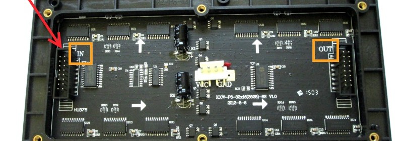
This is the second part of the 3-part article on how to hookup our 16×32 RGB LED panel kit to Arduino Uno. Click here to read the first part Step 3: Connecting the LED panel to the RGB connector shield The pin arrangement of the 2×8 IDC port (IN) on the back side of the RGB panel are shown below (image taken from Adafruit’s tutorial page). The 12 I/O pins of Arduino that are used to drive these signal lines are listed in the following table.

Read more
Hookup guide for 16×32 RGB LED panel – Part 1

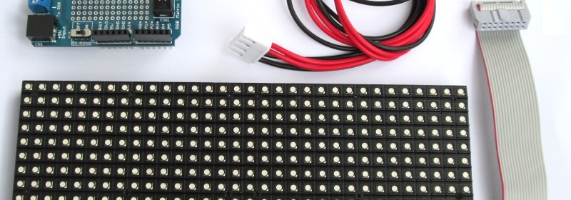
RGB LED panels are a great way of displaying colorful texts, images, and animation. In this 3-part tutorial, I am going to demonstrate how to hookup our 16×32 RGB LED panel kit to an Arduino Uno board and run some demo sketches. Our 16×32 RGB LED matrix panel kit includes everything you need to connect it to an Arduino Uno board. The kit includes: One 16×32 RGB LED matrix panel One RGB connector shield for Arduino Uno One IDC cable to connect the RGB matrix panel to the RGB shield One power supply connector for the RGB matrix Note that the power supply

Read more

New product: 16×32 RGB LED panel + Arduino Uno connector shield

Today, we have added a new and colorful product to our Tindie store. It is a colorful RGB LED matrix panel kit that includes a 16×32 RGB panel, a RGB connector shield for Arduino Uno, a 2×8 IDC cable, and a power supply connecting cable for the RGB panel. The RGB panel operates at 5V and requires 12 digital I/O pins of Arduino Uno for full control of the display. We designed the RGB matrix connector shield to allow super easy connection setup between the LED display panel and the Arduino Uno board. Features: Operates at 5V (2A rated power supply

Read more

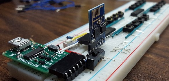
16-channel wifi remote using ESP8266

Hari Wiguna has shared on Hackaday.io this interesting scheme of making a 16-channel Wifi remote using ESP8266 and PCF8574 I/O expander chips. PCF8574 device provides an 8-bit I/O expansion for any microcontroller through an I2C interface. This Wifi remote consists of a transmitting remote unit and a receiving control unit, both of which use one ESP-01 module and two PCF8574 devices. The remote unit has 16 push switches connected to the PCF8574 I/O pins, whereas the receiving unit has 16 LEDs connected in a similar fashion to the two PCF8574 chips. The remote ESP-01 module operates as a web client that reads

Read more
« Older Entries Recent Entries »