Soldering instructions for the TrH Meter kit
|
|
First of all I would like to thank all of those who preordered the TrH Meter kits during the fundraising campaign that we ran on Tindie. It’s because of your support that we successfully launched this project. Please follow the soldering instructions provided below while building the TrH Meter.

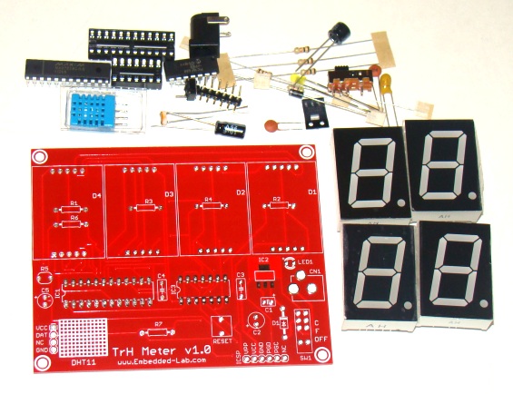
TrH Meter project kit
The kit contains total 29 items that are listed here.
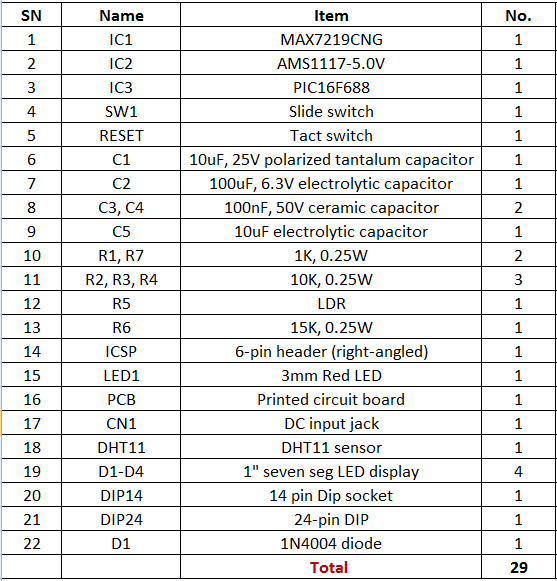
Components included in the kit
Important note: Some kits might contain Red LED displays instead of Yellow, and PCB color might also be Green instead of Red.
Step 1
The TrH Meter board contains all through-hole components except for IC2, which is the AMS1117-5.0 regulator IC in SOT-223 surface mount package. You should consider soldering this component first. It’s easier to solder a SMT package on a bare PCB than a populated one. Next solder all low profile components including resistors, LDR and diode.

Solder all low-profile components (AMS1117-5.0, resistors, LDR, and diode) first
Step 2
Next solder the capacitors, DIP IC sockets, switches and DC power supply connector. C1 is a polarized tantalum capacitor, so make sure you place it’s positive lead (which is usually longer than the cathode lead) to the hole marked with ‘+’.

Solder DIP IC sockets, capacitors, switches, and connector
Step 3
Solder the DHT11 sensor and four seven segment LED modules next. You can place the DHT11 sensor straight vertical or bend its legs at right angles to place it horizontal on PCB surface. Make sure Pin 1 of DHT11 goes to VCC hole on the PCB. After soldering the display modules, you can peel off the plastic cover from the display module for better readability.

Bend legs of DHT11 at right angles to place it horizontal on PCB

Peel off the plastic cover from displays for better readability
Step 4
You can solder the ICSP header if you want to modify/update the firmware. Otherwise it is optional, as the PIC microcontroller is already programmed.

ICSP header is optional and is required to update firmware
Now your project is ready to be powered. You can use a 6-12V DC wall adapter to power the TrH Meter. SW1 is a three position slide switch for ON/OFF, Fahrenheit or Celsius temperature selection. Once turned on, allow the sensor about 30 seconds for stable readings. If you want to play around with the firmware, visit the main document page to get the source code.
|
|
how much this kit. send price with shipment. thanks
For anyone interested I designed a case for this kit http://www.thingiverse.com/thing:62990
Built two units. No problems with construction or instructions. Worth noting that the DHT11 takes a few minutes to cool down after soldering.
Nice kit and thanks for your effort.
I just finished soldering the kit several minutes ago, including my first SMD part. I applied power and it worked perfectly the first time. Thanks for a great little project. Now I have to find someway to mount it.
Dennis, KC9PYD.
Replying to my previous post with the resolution:
It turns out to be the MAX7219 chip. It appears to have a short between pins 23 and 22. I tested it with another chip and everything worked fine. I contacted the author and he offered to send a replacement. Fantastic!
I just assembled this kit and I have a problem and was looking for help. When I turn on the kit all the 7 segment displays show the diagnostic pattern of all segments on. However when it starts reading the temp and humidity on each of the 7 segment displays the bottom most segments are not working.
I tried reseating the ICS but I am not really sure where to go from here. Help is appreciated.
Here my blog post for reference with pics http://www.3dprintmd.com/print/trh-meter-kit/
Pingback: TrH Meter Kit | 3D Printing