Tag Archives: ADC


Interfacing an external ADC chip to FPGA/CPLD

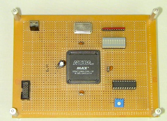
Chris (from PyroElectro) has posted an article on interfacing an external ADC chip to FPGAs and CPLDs, which do not have A/D capabilities built-in. He illustrates the idea with an Altera EPM7128 and a MAX150 8-bit analog to digital converter IC. The test analog signal is derived using a potentiometer and the converted digital output is shown using an LED bargraph display. The interface between the CPLD and ADC has been implemented in VHDL.

Interfacing an ADC to CPLD


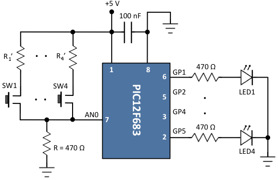
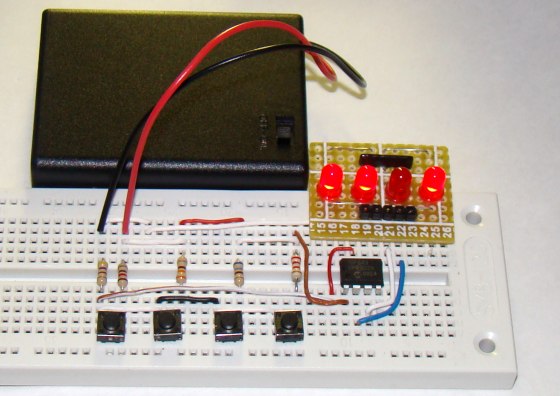
Connecting multiple tact switches on a single input pin of a microcontroller

Normally one tact switch requires one digital input pin of a microcontroller. Some designs implement keypad style multiplexing to get multiple switches on fewer inputs. However, there exist other techniques that allow you to connect many switches on a single input pin of a microcontroller. This tutorial demonstrates one such technique as applied to PIC12F683 microcontroller. In this example, there are four LEDs and four tact switches connected to the PIC12F683 microcontroller. While each LED is controlled through an individual I/O pin, the four switches are connected to one ADC input pin of the PIC12F683 microcontroller.

Connecting multiple tact switches to one input pin of PIC micro

Read more

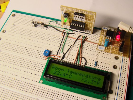
A Digital temperature meter using an LM35 temperature sensor

Introduction

A digital thermometer is a good choice of project for beginners who just stepped in to the world of microcontrollers because it provides an opportunity to learn using sensors to measure the real world signals that are analog in nature. This article describes a similar project based on a PIC16F688 microcontroller and an LM35 temperature sensor. LM35 is an analog sensor that converts the surrounding temperature to a proportional analog voltage. The output from the sensor is connected to one of the ADC channel inputs of the PIC16F688 microcontroller to derive the equivalent temperature value in digital format. The computed temperature is displayed in a 16×2 character LCD, in both °C and °F scales.

Theory

The LM35 series of temperature sensors are produced by National Semiconductor Corporation and are rated to operate over a -55 °C to 150°C temperature range. These sensors do not require any external calibration and the  output voltage is proportional to the temperature. The scale factor for temperature to voltage conversion is 10 mV per °C. The LM35 series sensors come in different packages. The one I used is in a hermatic TO-46 transistor package where the metal case is connected to the negative pin (Gnd).

Read more

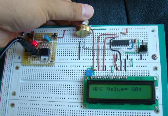
Lab 5: Analog-to-digital conversion (ADC)

Description

Analog-to-digital conversion (ADC) is necessary because, while embedded systems deal with digital values, their surroundings typically involve many analog signals such as, temperature, speed, pressure, the output of a microphone, etc. They all need to be converted into digital data before being processed by the microcontroller. Today, we will see how to read an external analog signal using a PIC16F688 microcontroller, and display the conversion output (a digital number) on a LCD. The input analog signal will be a varying voltage between 0-5V derived using a potentiometer.

Required Theory

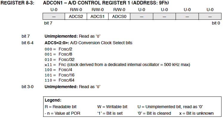
The PIC16F688 microcontroller has a built-in 10-bit ADC with eight input channels. The eight channels are available at RA0, RA1, RA2, RA4, RC0, RC1, RC2, and RC3. They have alternate labels, AN0-AN7, for this function, and are multiplexed into a single Sample and Hold circuit. The output of the Sample and Hold is connected to the input of the A/D converter. The 10-bit conversion result is stored  into the ADC result registers ADRESH (A/D Result Higher byte) and ADRESL (A/D Result Lower byte). Each of these registers is 8-bit. The functionality of the A/D module is controlled by three registers: ANSEL, ADCON0, and ADCON1. The details of these control registers are discussed in ADC channels in PIC16F688.
Read more
ADC channels in PIC16F688

The PIC16F688 microcontroller has a built-in 10-bit ADC with eight input channels. The eight channels are available at RA0, RA1, RA2, RA4, RC0, RC1, RC2, and RC3. They have alternate labels, AN0-AN7, for this function, and are multiplexed into a single sample and Hold circuit. The output of the sample and hold is connected to the input of the A/D converter. The A/D conversion is successive approximation based and the 10-bit result is stored  into the ADC result registers ADRESH (A/D Result Higher byte) and ADRESL (A/D Result Lower byte). Each of these registers is 8-bit.

Pin diagram of the PIC16F688 microcontroller

Read more

Recent Entries »